98 ZX2 GAS-INSULATED MEDIUM VOLTAGE SWITCHGEAR
7.4. Outlet filter
Low voltage compartments with operating
currents > 2000 A are fitted with outlet filters.
The outlet filters are located on the roof plates of
the low voltage compartments. Replace the filter
mats when required.
Draw the louvred grating off by gripping the
recesses at the bottom end of the filter. Replace
the filter mat and snap the louvred grating back
into position.
—
7. Service
7.1. Inspection and maintenance of the
switchgear
• Check that the switchgear room and the switch-
gear are in proper condition for the intended
use at regular intervals.
• Check primarily for dirt, corrosion and mois-
ture.
Hazard warning
If you find that the switchgear is not in
the proper condition, take appropriate
action, e.g. cleaning of the switchgear,
removal of corrosion or rectification of
the cause of the moisture.
7.2. Inspection and servicing of individual
components
Please consult the relevant directions and
instruction manuals for the actions and intervals
required.
All parts in SF
6
are maintenance-free.
The three position disconnect is maintenance-
free for 2000 operating cycles, and the
disconnect for 1000 operating cycles.
7.3. Checking the dimensional accuracy of the
control wire settings
Check the play on the control wires on the circuit-
breaker operating mechanism in the course of an
inspection.
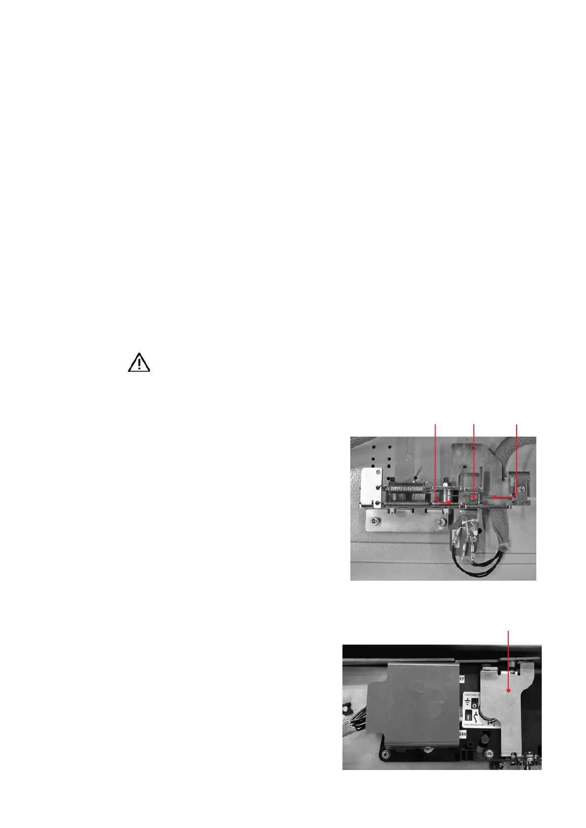
The mounting for the control wires of the
mechanical interlock is located above the circuit-
breaker operating mechanism (fig. 6.3.1).
When the access interlock for the three-position
disconnect mechanism (fig. 6.3.2) is opened, the
slide must be directly operated by the control
wire. If this is not the case, use the control wire
nipple to adjust the control wire so that there is
no play with the flap closed.
—
Fig. 7.3.2
—
Fig.7.3.1
—
Fig. 7.3.1:
Mounting for the
control wire above
the circuit-breaker
operating mechanism
—
Fig. 67.3.2:
Mechanical access
interlock on the
three-position dis-
connect mechanism
Mechanical access interlock
Slide
Control wire
nipple
Control
wire