72 ZX2 GAS-INSULATED MEDIUM VOLTAGE SWITCHGEAR
Hazard warning
•
is voltage-free.
5.2.3.2. Grounding the busbar via grounding and
short-circuiting device
• Ground a feeder panel via the three-position
disconnector and the circuit breaker as de-
scribed in chapters 5.2. and 5.2.1.
Hazard warning
• Check the feeder for absence of voltage
as described in chapter 5.1.
• Always observe the five safety rules set
Procedure for panels with cable sockets (inner
• Dismantle the rear cover of the cable compart-
ment.
• Dismantle blind plugs, voltage transformers
(chapter 3.3.7) or surge arresters from the test
sockets of the panel.
• Clean the current test plug to be fitted below.
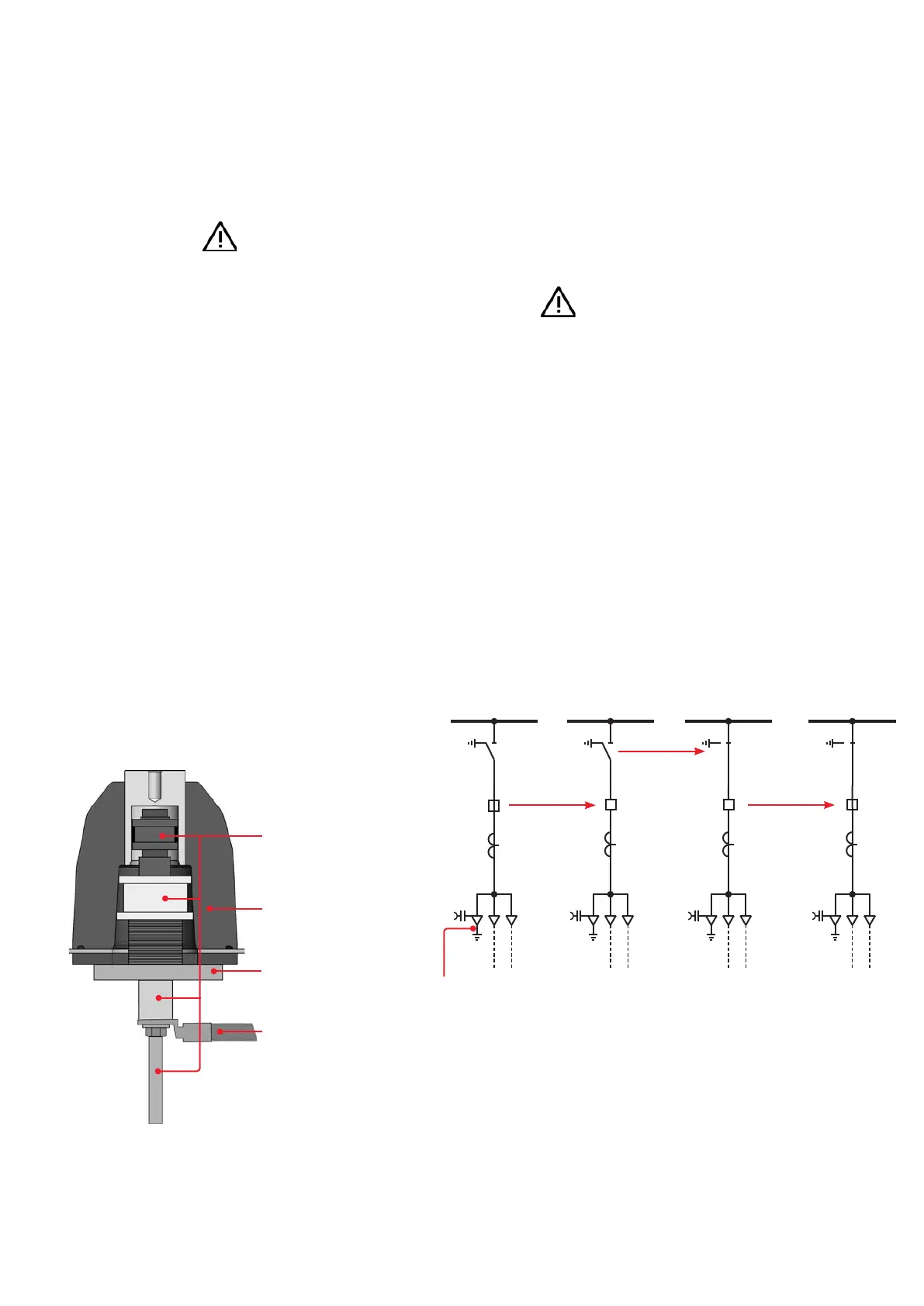
Current
test plug
Flange of the
test plug
Three-pole ground-
ing and short-cir-
cuiting device
Test socket
of the panel
—
Fig. 5.2.3.2.1:
Connection of an
grounding and short-
circuiting device
to a test socket of
a feeder panel with
inner cone system (only
one phase shown)
• Insert the current test plug into the test socket
and screw its flange onto the test socket.
• Proceed in the same way with the other two
phases.
• Connect a three-pole grounding and short-cir-
cuiting device to the previously mounted cur-
rent test plugs and the main grounding bar of
the installation.
• Carry out the switching operations as described
below (Fig. 5.2.3.2.2)
—
Fig. 5.2.3.2.2
Switching operations for grounding the busbar
1) Switch the circuit breaker "OFF".
2) Switch the three-position disconnector from the grounding
to the "disconnector ON" position.
3) Switch the circuit breaker "ON".
4) The busbar is grounded via the grounding and short-circuit
ing device.
—
Fig. 5.2.3.2.1
—
Fig. 5.2.3.2.2:
Switching operations for
grounding the busbar
Three-pole ground-
ing and short-cir-
cuiting device