5. OPERATION 73
Procedure for panels with outer cones
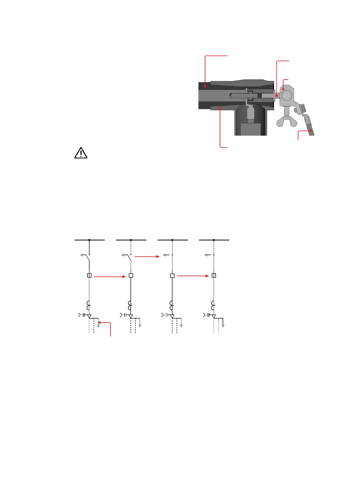
The three-pole grounding and short-circuiting
device is connected via manufacturer- and
type-specific, current-carrying terminations of
the cable connector systems used.
• Dismantle the rear cover of the cable compart-
ment.
• Install the current-carrying terminations ac-
cording to the cable connector system manu-
facturer's instructions.
• Connect a three-pole grounding and short-cir-
cuiting device to the previously installed cur-
rent-carrying terminations and the main
grounding bar of the system.
• Carry out the switching operations as described
below (Fig. 5.2.3.2.4)
Hazard warning
•
is voltage-free.
Three-pole ground-
ing and short-cir-
cuiting device
Termination
Outer cone
of the panel
Cable
connector
—
Fig. 5.2.3.2.3
—
Fig. 5.2.3.2.3:
Connection of an
grounding and short-
circuiting device to
a feeder panel with
outer cones (only
one phase shown)
—
Fig. 5.2.3.2.4:
Switching operations for
grounding the busbar
—
Fig. 5.2.3.2.4
Three-pole ground-
ing and short-cir-
cuiting device
Current-carrying
terminations
Switching operations for grounding the busbar
1) Switch the circuit breaker "OFF".
2) Switch the three-position disconnector from the grounding
to the "disconnector ON" position.
3) Switch the circuit breaker "ON".
4) The busbar is grounded via the grounding and short-circuit
ing device.