36 ZX2 GAS-INSULATED MEDIUM VOLTAGE SWITCHGEAR
• Release the gas (N
2
) from the relevant busbar
compartment into the atmosphere by pressing
the valve pin (see HB 645 en) until the pressure
is equalised.
• Dismantle the transport lid on the heat sink and
the pressure relief lid on the busbar compart-
ment.
• Remove the transport drying agent bags from
the gas compartments and replace them with
new bags with the same quantity of drying
agent. Continue assembly immediately, so as
not to impair the effectiveness of the drying
agent material.
• Clean the sealing surfaces of the busbar com-
partment, the heat sink and the sealing ring
with a dry, clean, non-fraying cloth.
Important note
Thinly grease the entire surface of the
sealing ring with silicone paste.
• Set the sealing ring on the roof plate of the bus-
bar compartment and align it symmetrically to
the opening. Use suitable lifting gear to set the
heat sink on the busbar compartment in such a
way that the relevant stud bolts in the busbar
enclosure engage in the bores in the flange
plate on the heat sink, taking care to ensure that
the sealing ring is correctly positioned in the
slot of the heat sink flange.
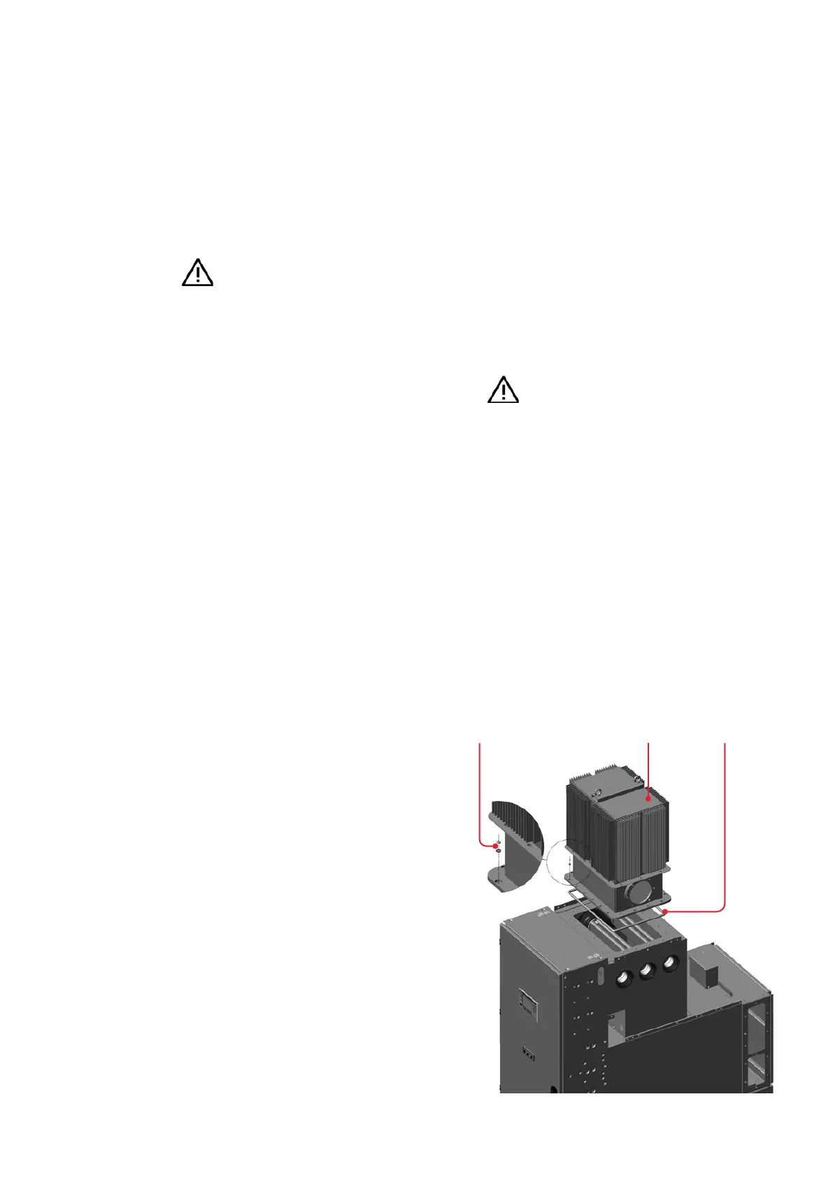
3.3.4. Installation of the heat sinks
Heat sinks fitted on the busbar compartment for
rated currents > 2500 A are as a rule supplied sep-
arately and installed after the panels have been
set up.
The relevant busbar compartments are filled with
N
2
(nitrogen) for transport. (With regard to the
gas work required, consult instruction manual
HB 645 en – use of SF
6
insulating gas).
Important note
The weight of a heat sink is approx.
200 lbs. Use suitable lifting gear (e.g. a
heat sinks. We recommend having
installation performed by two fitters.
Observe the relevant accident prevention
regulations in the country of installation.
• Follow the installation drawings supplied when
fitting the heat sinks.
Assembly must take place in as clean (dust-free)
conditions as possible.
—
Fig.3.3.4.1:
Installation of
the heat sinks
Sealing
ring
Heat
sink