3. INSTALLATION OF THE SWITCHGEAR AT SITE 37
• Align the bores in the flange plate so that they
are centered around the stud bolts.
• Fasten the heat sink across the diagonal at all
stud bolts, using washers, spring washers and
nuts, with a torque of 9.2 ft·lb (for unlubricated
stud bolts).
• Evacuate and fill the gas compartment (busbar
compartment + heat sink) with SF
6
as described
in manual HB 645 en. Check the gas compart-
ment for leakage.
3.3.5. Installation of the top-mounted box for
the busbar metering system with isolating de-
vice
The adapter box required for this variant is fitted
at the factory. Top-mounted boxes for busbar
metering systems with isolating devices are
generally delivered separately and have to be
installed after the panels have been set up.
The relevant busbar compartments with adapter
box are filled with N
2
(nitrogen) for transport.
(With regard to the necessary gas work, see
manual HB 645 en – Use of SF
6
insulating gas.)
Important note
A top-mounted box weighs approx.
232 lbs. Use suitable lifting gear (e.g. a
mounted box. We recommend having two
fitters perform the installation work.
Please observe the accident prevention
regulations in the country of installation.
Installation of the top-mounted box on the front
busbar compartment is described below. The
procedure is similar for Installation of the top-
mounted box on the rear busbar compartment.
Installation of the top-mounted box
Observe the installation drawings supplied when
installing the top-mounted boxes.
Installation must take place in a dry place with as
little dust as possible.
• Press in the valve pin (see HB 645 en) to release
the gas (N
2
) in the relevant busbar compartment
and top-mounted box into the atmosphere.
• Remove the transport lids from the adapter box
and the top-mounted box. The reinforcement
strips to be removed in that process are re-
quired later for installation of the top-mounted
box.
• Remove the side assembly cover from the top-
mounted box.
• Remove the drying agent bags from the busbar
compartment.
• Clean the sealing surfaces of the adapter box
and the top-mounted box and the sealing ring
with a dry, clean and non-fraying cloth.
Important note
Thinly grease the entire surface of the
sealing ring with silicone paste.
• Lay the sealing ring in the slot on the adapter
box. Use a suitable hoist to position the top-
mounted box on the adapter box in such a way
that the relevant welded stud bolts on the top-
mounted box engage in the bores in the flange
plate of the adapter box, ensuring that the
sealing ring is correctly positioned in the slot on
the adapter box.
• To strengthen the flange, position the
reinforcement strips (4 pcs., see fig. 3.3.5.2,
bottom) before fitting the washers, spring
washers and nuts to the stud bolts. Tighten the
nuts across the diagonal with a torque of
9.2 ft·lb ( stud bolts ungreased).
—
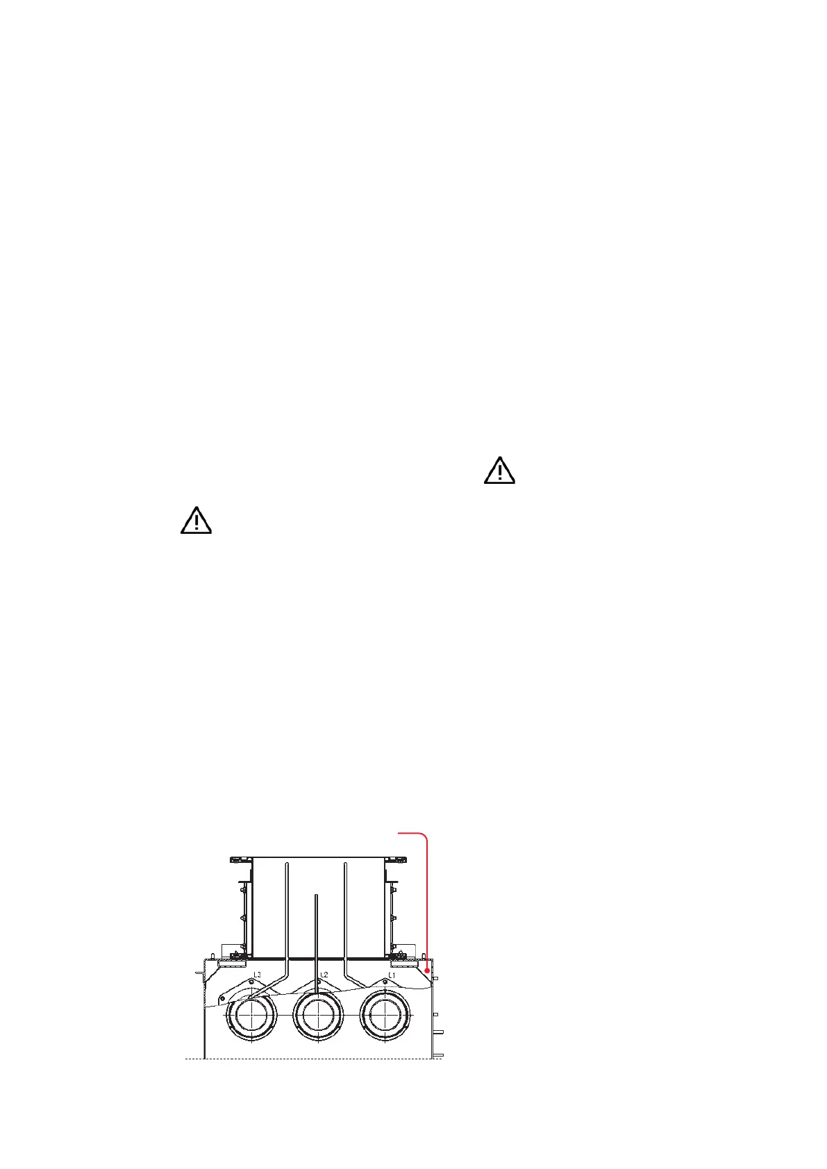
Fig. 3.3.5.1:
Position of the drying
agent bag in the
busbar compartment
Drying agent bag