60 ZX2 GAS-INSULATED MEDIUM VOLTAGE SWITCHGEAR
3.3.7.7. Installation of damping resistors
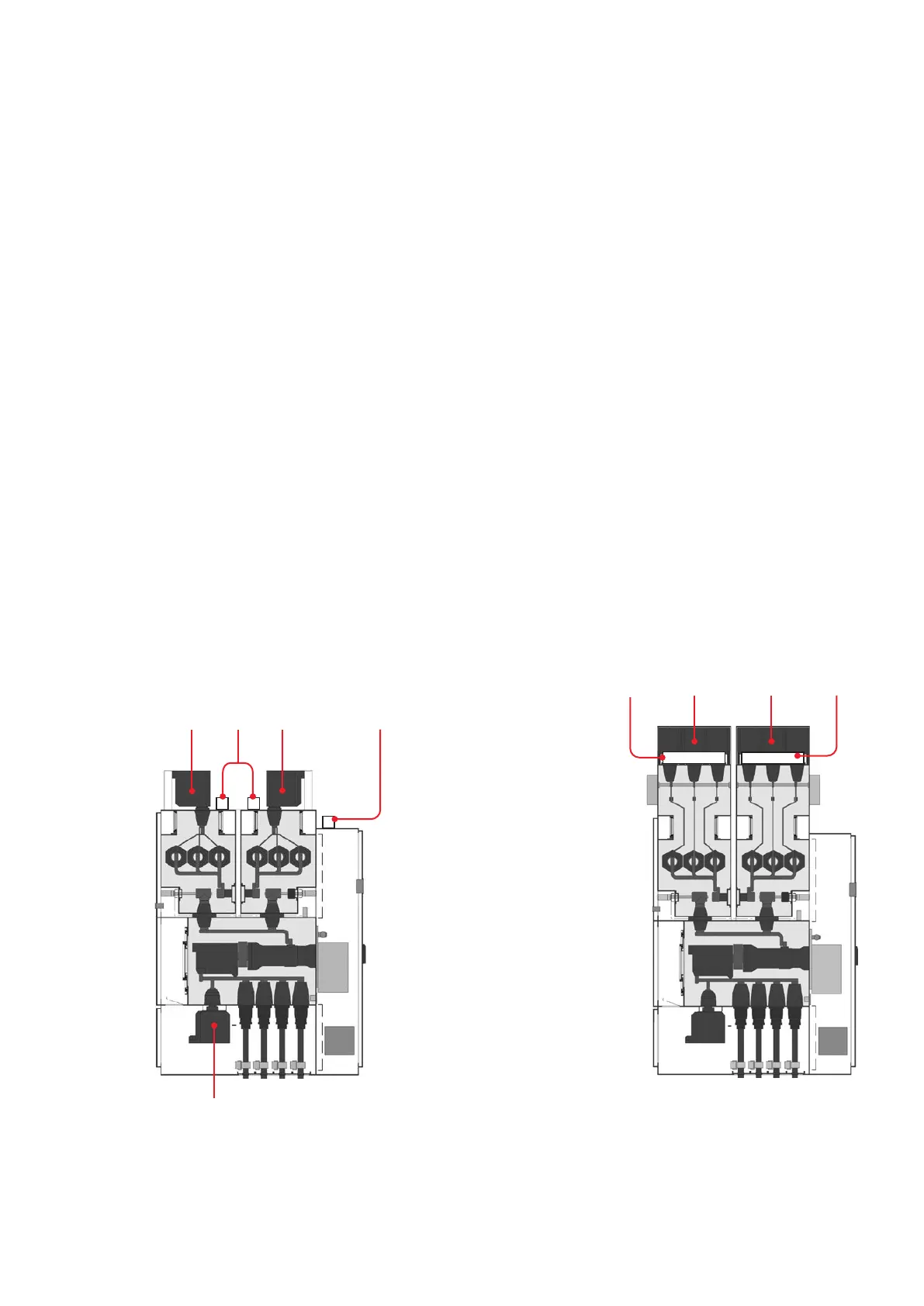
Damping resistors, if required, are usually
mounted on site. The intended position depends
on the type of the panel. Take the respective posi-
tion of Fig. 2.3.7.7.1a and b.
Wiring of the damping resistors
The damping resistors have several taps. The
clamps of the taps are marked with resistance
values in ohms (Fig. 3.3.7.7.2). Take the required
resistance from the circuit diagram and connect
the damping resistor according to the wiring dia-
gram.
Attach the damping resistor according to the sup-
plied assembly drawings.
—
Fig. 3.3.7.7.1a:
Position of damp-
ing resistors
Metering 2
Metering 1
Metering 2 Metering 2
Metering 3Metering 3
Metering 1