3. INSTALLATION OF THE SWITCHGEAR AT SITE 45
• First crank the voltage transformer up by a few
centimeters only and ensure that the silicone in-
sulating part of the voltage transformer can be
inserted into the socket without obstruction.
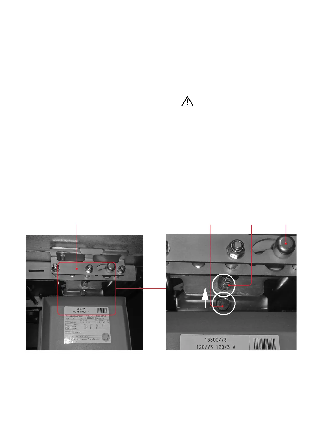
Crank the voltage transformer up until the bore
in the retaining plate of the transformer is
aligned with the locking pin (fig. 3.3.7.2.2). This
is the case when the locking plate can be
pressed into the locking position.
• When the locking plate has been pressed into
the locking position, slide the locking knob to
the left into its limit position (fig. 3.3.7.2.2). The
voltage transformer is then fixed in the correct
position.
• Lower the voltage transformer truck by turning
the crank until the stop is reached.
• Disengage the assembly aid (fig. 3.3.7.1.5) and
remove it from the cable termination compart-
ment.
• Wipe any surplus grease off from the area of the
voltage transformer flange below the voltage
transformer’s plug-in connection as far as pos-
sible.
• Install the further voltage transformers in the
same way.
• Fit the retaining plate and secure it with the
padlock (fig. 3.3.7.1.2).
• Insert the secondary side plugs into the sockets
provided on the voltage transformers and lock
the plugs in place with the integrated clamps or
wire the transformers as set out in section
3.3.7.9 if a terminal box is provided.
Important note
assigned to the relevant voltage
transformers.
• Refit the lower crossbar in the cable termination
compartment. (fig. 3.3.7.1.1).
• Fit and screw in the cover of the cable termina-
tion compartment.
—
Fig. 3.3.7.2.2:
Cranking the voltage
transformer up
until the locking pin is
aligned with the bore
Locking plate
Bore in the retaining plate
of the transformer Locking pin Locking knob