3. INSTALLATION OF THE SWITCHGEAR AT SITE 53
• Screw the hexagonal pins to the stud bolts on
the enclosure (tightening torque 9.2 ft·lb) as
shown in fig. 3.3.7.5.1.
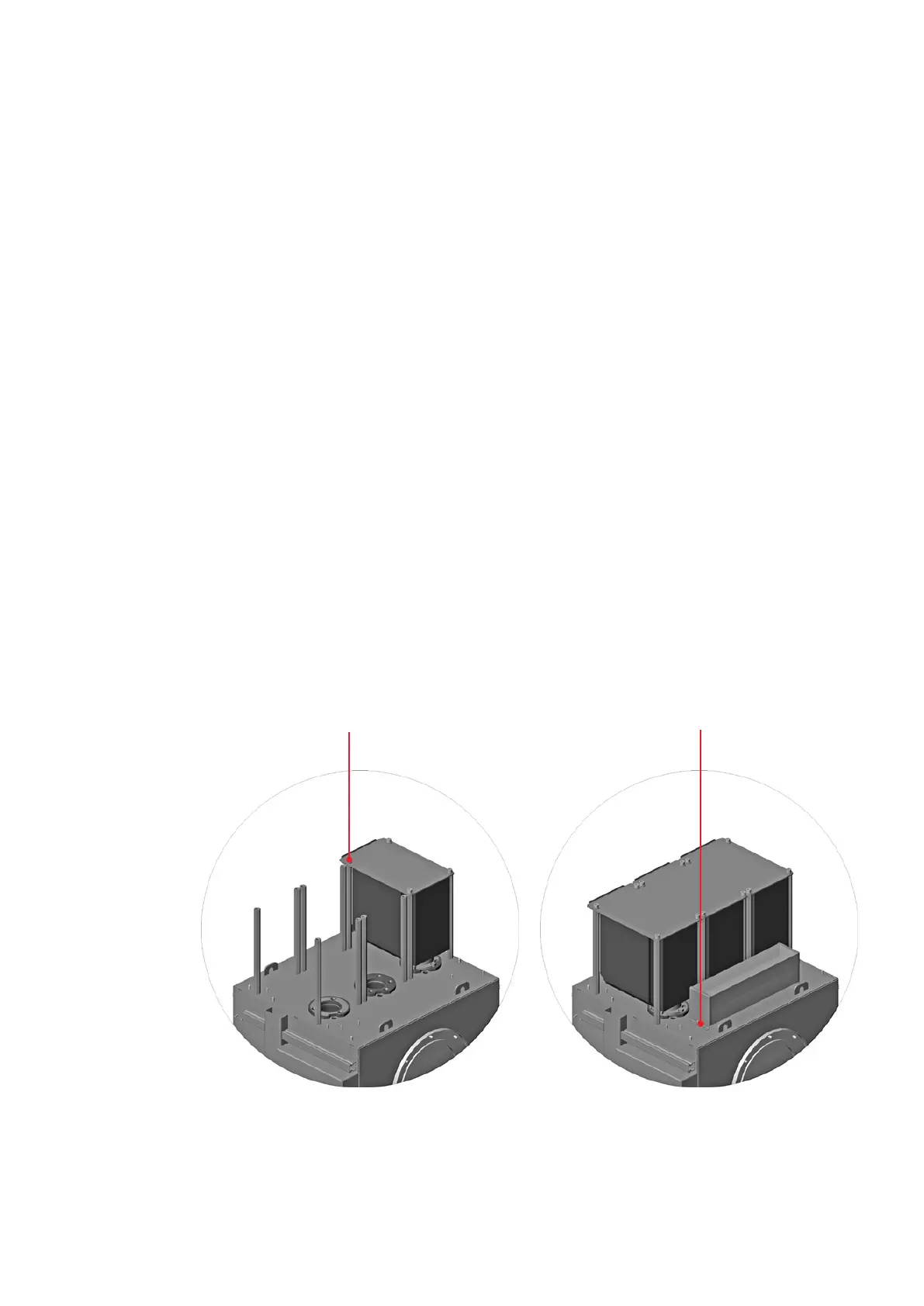
• Slowly and carefully insert the transformer into
the socket. The plug-in connection must slide
easily into the corresponding socket. Check the
position of the silicone parts in relation to the
socket continuously and correct if necessary.
A counter-pressure will become noticeable ap-
prox. 0.8 in before the limit position is reached.
(Fig. 3.3.7.5.2).
• Fasten the transformer cover to the previously
fitted fastening bracket and to the top plates of
the voltage transformers (fig. 3.3.7.5.1 and 2).
• Install the further voltage transformers in the
same way.
• Wire the transformers as set out in section
3.3.7.6.
• If required, wire and mount the damping resis-
tor according to fig. 3.3.7.5.3 and chapter 3.3.7.7.
—
Fig. 3.3.7.5.2:
Fastening of the
voltage transformer
—
Fig. 3.3.7.5.3:
Fastening of the
damping resistor
—
Fig. 3.3.7.5.2
—
Fig. 3.3.7.5.3
4 x cheese head screw M 10 x 25 DIN 912
4 x dished washer 10 DIN 6796
2 x washer A 5,3 DIN 433
2 x spring washer A 5 DIN 127
2 x hexagonal nut M 5 DIN 934