80 ZX2 GAS-INSULATED MEDIUM VOLTAGE SWITCHGEAR
Conditions for operations
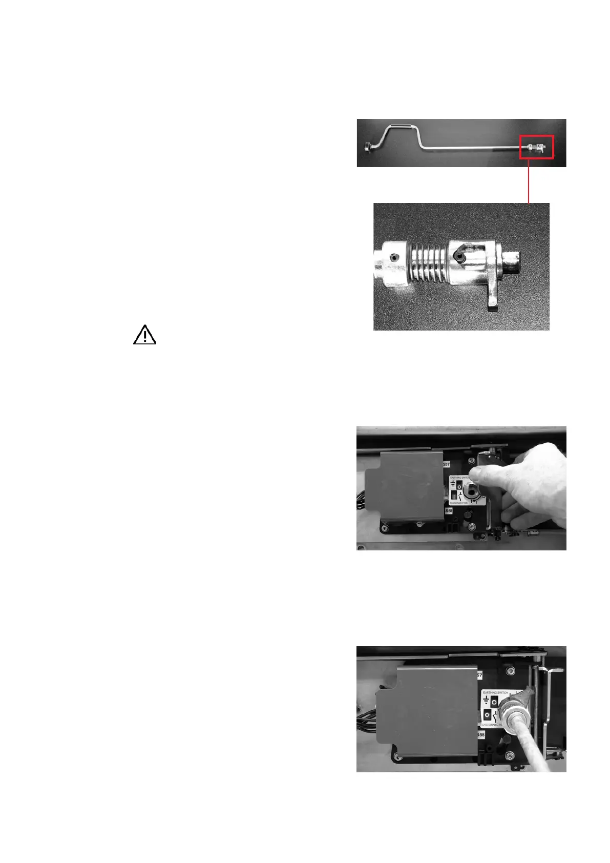
• A crank is required for manual operation of the
switch (fig. 5.5.2.4).
• Observe the switch position indicator before
operating the three position disconnect or the
disconnect.
• Switch the circuit-breaker in the relevant panel
off.
• If fitted: Swing the flap of the mechanical
access lock to the right (fig. 5.5.2.5). (It is not
possible to move the flap when the circuit-
breaker is closed.)
• In double busbar systems, when the mechanical
access lock is used, the three position
disconnect and the disconnect in a panel are
interlocked. It is possible to move the flap of
one switch when the other switch is in the OFF
position.
• Insert the crank into the shaft of the three
position disconnect mechanism (fig. 5.5.2.6).
Hazard warning
Always perform switching operations
right up to the stop.
Operation of the three-position disconnect
When using the crank, ensure that pressure is
continuously applied via the mushroom handle at
the end of the crank throughout the complete
switching operation.
Approx. 24 turns of the crank are required from
the OFF position of the three position disconnect
to the ON position of the grounding switch or
disconnect and vice versa.
• Grounding switch OFF ON
- To close the grounding switch, turn the crank
counter-clockwise until the stop is reached.
- Withdraw the crank.
- Close the flap of the mechanical access lock.
• Disconnect OFF ON
- To close the disconnect, turn the crank
clockwise until the stop is reached.
- Withdraw the crank.
- Close the flap of the mechanical access lock.
—
Fig. 5.5.2.4:
Crank for emergency
manual operation of the
three-position discon-
nect and the disconnect
—
Fig. 5.5.2.5:
Opening the flap of the
mechanical access lock
—
Fig. 5.5.2.6:
Inserting the crank
into the shaft of the
operating mechanism
—
Fig. 5.5.2.4
—
Fig. 5.5.2.5
—
Fig. 5.5.2.6