MC81F4204
April 24, 2012 Ver.1.41 101
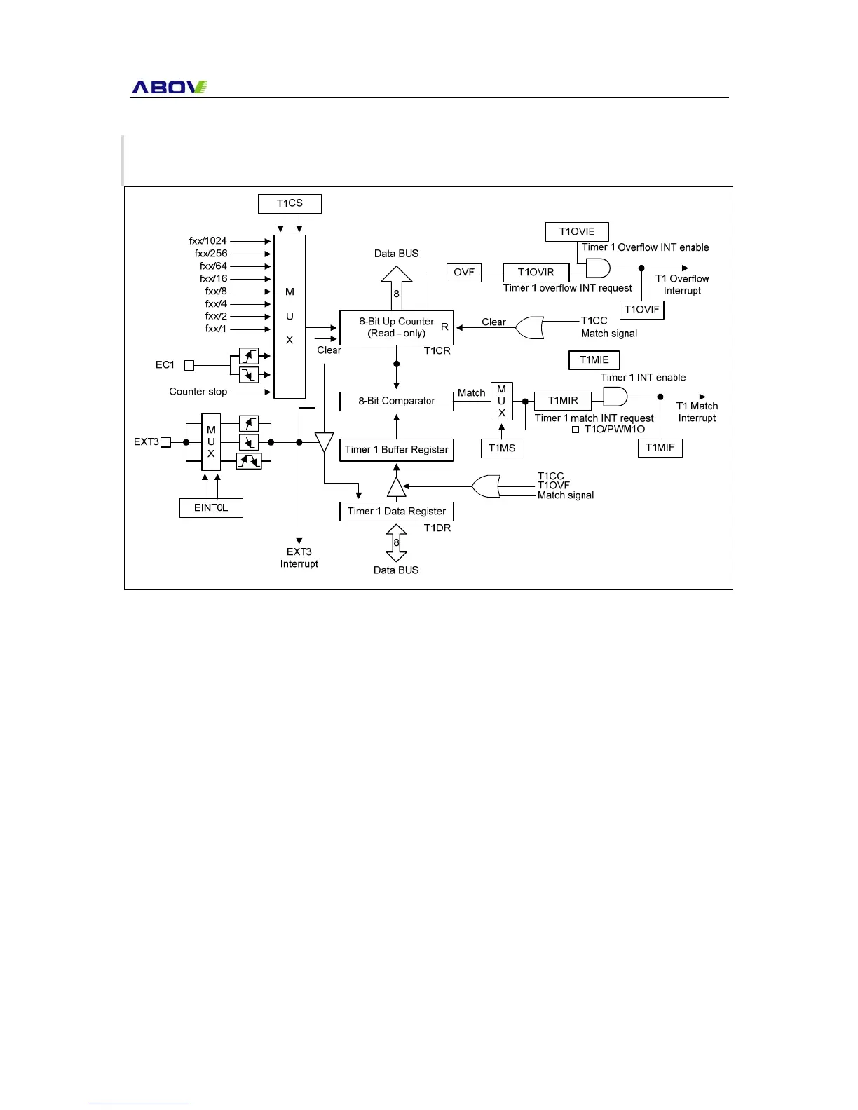
16.3 Timer 1 8-Bit Mode
Timer 1 has the following functional components:
- Clock frequency divider (fxx divided by 1024, 256, 64, 16, 8, 4, 2, 1) with multiplexer
- External clock input pin, EC1 (R04)
- I/O pins for capture input, EXT3 (R05) or PWM or match output PWM1O/T1O (R05)
- 8-bit counter (T1CR), 8-bit comparator, and 8-bit reference data register (T1DR)
- Timer 1 status and control register (T1SCR)
- Timer 1 overflow interrupt and match interrupt generation
Figure 16-2 8-bit Timer 1 Block Diagram