MC81F4x16
36 April 24, 2012 Ver.1.41
7.13 Internal RC Oscillation Characteristics
(T
A
= - 40
°
C to + 85
°
C, V
DD
= 2.2 V to 5.0 V)
Parameter Symbol Conditions Min Typ. Max Units
V
DD
=5.0V, T
A
= 25
°
C
-4% 8.0 4%
RC oscillator
frequency (1)
fIRC
V
DD
=5.0V,
T
A
= – 40
°
C to + 85
°
C
-20% 8.0 20%
MHz
Clock duty ratio TOD – 40 50 60 %
RC oscillator setup
time
(2)
tSUIRC
T
A
= 25
°
C
– – 10 mS
NOTES:
1. Data based on characterization results, not tested in production
2. X
IN
and X
OUT
pins can be used as I/O ports.
7.14 Main Oscillation Stabilization Time
(T
A
= - 10
°
C to + 70
°
C, V
DD
= 2.2 V to 5.5 V)
Oscillator Conditions Min Typ. Max Units
Crystal – – 60 mS
Ceramic
fx > 1 MHz
Oscillation stabilization occurs when
V
DD
is equal to the minimum
oscillator voltage range.
– – 10 mS
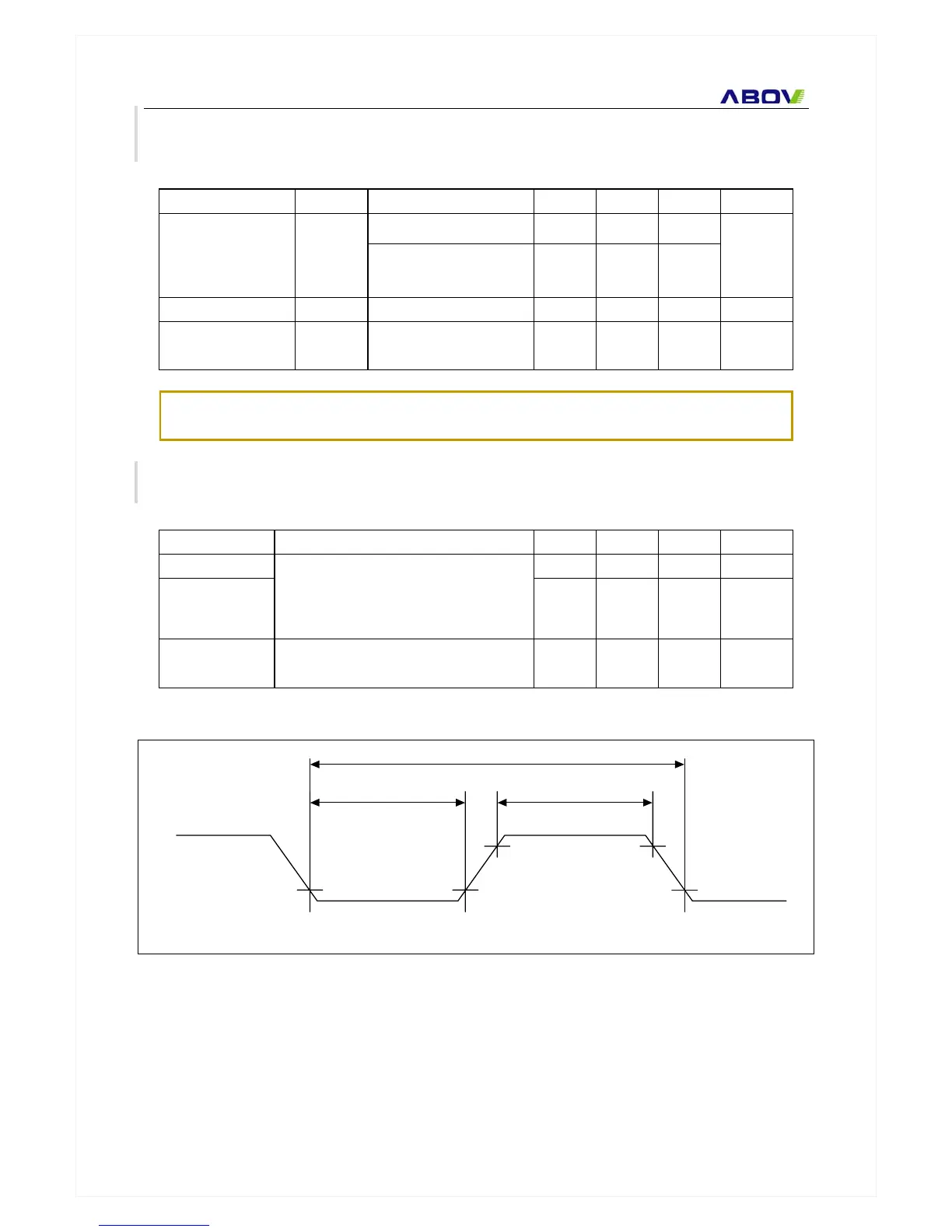
External Clock
X
IN
input high and low width (t
XH
,
t
XL
)
40.0 – 480 nS
XIN
0.8VDD
0.2VDD
tXHt XL
1 / fx
Figure 7-9 Clock Timing Measurement at XIN