MC81F4204
April 24, 2012 Ver.1.41 111
19. BUZZER
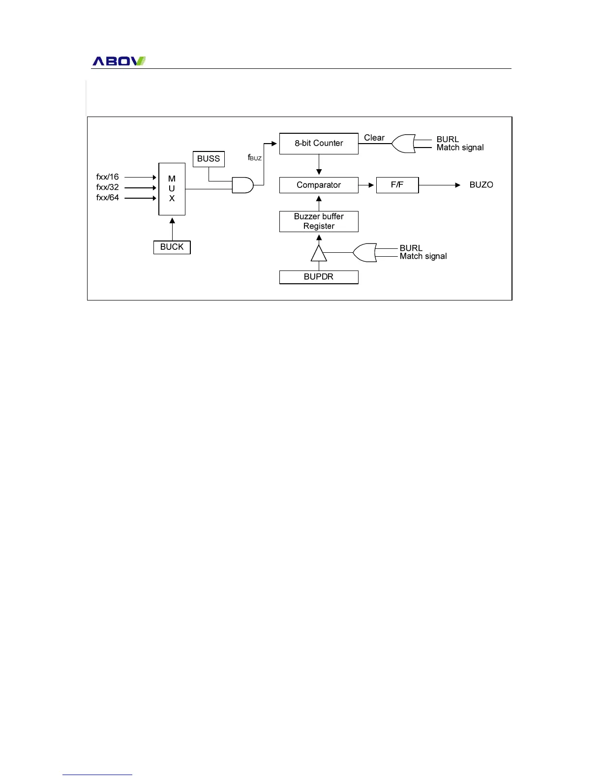
The buzzer driver consists of 8-bit binary counter, the buzzer period data register BUPDR, and the
buzzer driver register BUZR, the clock selector. It generates square-wave which is very wide range
frequency (244 Hz ~ 250 KHz at f
xx = 8MHz) by user programmable counter.
Pin R12/BUZO is assigned for output port of Buzzer driver by setting the bits R12 of R1 Control
Middle Register (R0CONM) to “101”.
The 8-bit buzzer counter is cleared and start the counting by writing signal to the register BUZR. It is
increased from 00
H until it matches with BUPDR[7:0].
Also, it is cleared by counter overflow and count up to output the square wave pulse of duty 50%.
The bit 0 to 7 of BUPDR determines output frequency for buzzer driving. BUPDR is initialized to FFH
after reset.
Frequency calculation is following as shown below.
Figure 19-1 Buzzer Driver Block Diagram