MC81F4204
88 April 24, 2012 Ver.1.41
13. OSCILLATION CIRCUITS
There are few example circuits for main oscillators.
Oscillation circuit is designed to be used either with a ceramic resonator or crystal oscillator. Since
each crystal and ceramic resonator have their own characteristics, the user should consult the crystal
manufacturer for appropriate values of external components.
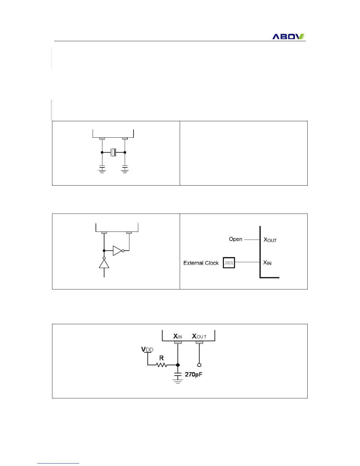
13.1 Main Oscillation Circuits
C1
C2
X
IN
X
OUT
C1, C2 = 10 ~ 30 pF
* The example load capacitor value(C1, C2) is
common value but may not be appropriate for
some crystal or ceramic resonator.
X
IN
X
OUT
Xout pin can be used as a normal pin.
Figure 13-1 Crystal/Ceramic Oscillator
Figure 13-2 External Clock
Figure 13-3 External RC Oscillator