MC81F4204
140 April 24, 2012 Ver.1.41
25.3 Hardware Conditions to Enter the ISP Mode
Anytime RESET/ Vpp pin goes +9V, the MCU entering an ISP mode except RESET/Vpp pin is
output mode(See note1).
1. If other signals affect SIO communication in ISP mode, disconnect these pins by using a jumper or
a switch.
Note:
1) Using RESET/Vpp pin as an output mode is not recommended even it is possible.
Anytime RESET/Vpp pin goes +9v, the MCU entering an ISP mode except RESET/Vpp pin
is output mode. If it is output mode, +9v signal is clashing with the output voltage.
So if RESET/Vpp pin is used as an output mode, do not try to execute any ISP commands
when MCU is in normal operation mode. It is allowable when only power on time. See
‘Entering ISP mode at power on time’ for more information.
2) There is a 10KΩ pull-down register at VPP pin in the ISP Board. That is why 75KΩ
register is suggested for R/C reset circuit. So those two register makes a voltage divider
circuit when ISP board is connected. So the VPP level can’t go down to low level status if the
register of reset circuit value is too small. Otherwise, if the register value is too large the
capacitor value also changed and the reset circuit’s characteristics also changed.
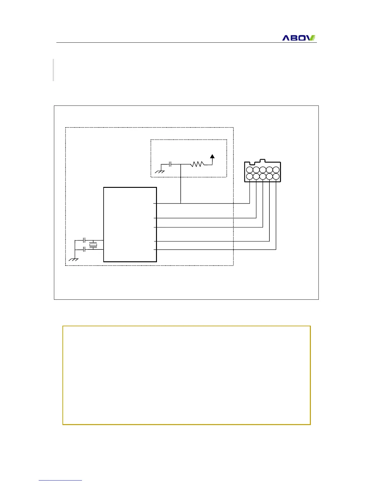
Figure 25-2 Hardware Conditions to Enter the ISP Mode
RESET/Vpp
SDATA
SCL