MC81F4204
78 April 24, 2012 Ver.1.41
INTFH
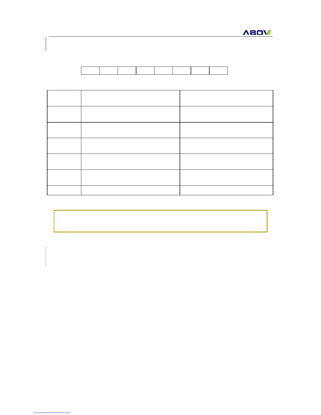
INTERRUPT FLAG HIGH REGISTER 00EEH
7 6 5 4 3 2 1 0
INTFH
T0MIF T0OVIF T1MIF T1OVIF T2MIF T2OVIF
Reset value: 00H
R/W R/W R/W R/W R/W R/W R/W R/W
0: No generation
T0MIF
Timer 0 Match Interrupt Flag Bit
1: Generation
0: No generation
T0OVIF
Timer 0 Overflow Interrupt Flag Bit
1: Generation
0: No generation
T1MIF
Timer 1 Match Interrupt Flag Bit
1: Generation
0: No generation
T1OVIF
Timer 1 Overflow Interrupt Flag Bit
1: Generation
0: No generation
T2MIF
Timer 2 Match Interrupt Flag Bit
1: Generation
0: No generation
T2OVIF
Timer 2 Overflow Interrupt Flag Bit
1: Generation
-
bit 1 – bit 0 Not used for MC81F4204
Note:
When you use ‘Shard Interrupt Vector’, those INTFH is used to recognize which interrupt is
generated. See ‘11.4 Shared Interrupt Vector’ on page 81 for more information.
11.2 Interrupt Sequence
An interrupt request is held until the interrupt is accepted or the interrupt latch is cleared to “0” by a
reset or an instruction. Interrupt acceptance sequence requires 8 cycles of fXIN (1μs at fXIN=
4MHz) after the completion of the current instruction execution. The interrupt service task is
terminated upon execution of an interrupt return instruction [RETI].
Interrupt acceptance
1. The interrupt master enable flag (I-flag) is cleared to “0” to temporarily disable the acceptance
of any following maskable interrupts. When a non-maskable interrupt is accepted, the
acceptance of any following interrupts is temporarily disabled.
2. Interrupt request flag for the interrupt source accepted is cleared to “0”.
3. The contents of the program counter (return address) and the program status word are saved
(pushed) onto the stack area. The stack pointer decreases 3 times.
4. The entry address of the interrupt service program is read from the vector table address and
the entry address is loaded to the program counter.
5. The instruction stored at the entry address of the interrupt service program is executed.