MC81F4204
108 April 24, 2012 Ver.1.41
over. And it can be maintained the duty value at present output when changed only period value
shown as Example of PWM2. As it were, the absolute duty time is not changed in varying frequency.
Note :
When user need to change mode from the Timer2 mode to the PWM mode, the Timer2
should be stopped firstly, and then set period and duty register value. If user writes register
values and changes mode to PWM mode while Timer2 is in operation, the PWM data would
be different from expected data in the beginning.
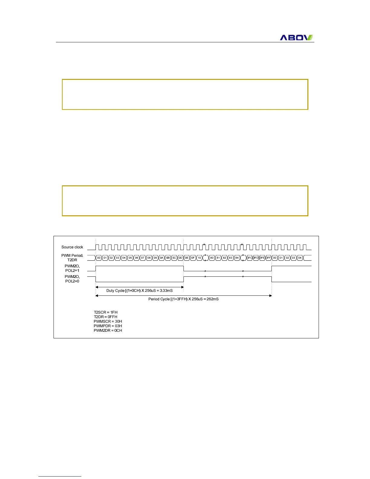
PWM Period = [PWMPDR[1:0]T2DR+1] X Source Clock
PWM2 Duty = [PWMPDR[3:2]PWM2DR+1] X Source Clock
PWM3 Duty = [PWMPDR[5:4]PWM3DR+1] X Source Clock
If it needed more higher frequency of PWM, it should be reduced resolution.
Note :
If the duty value and the period value are same, the PWM output is determined by the bit
POL (1: High, 0: Low). And if the duty value is set to “00H”, the PWM output is determined by
the bit POL(1: Low, 0: High). The period value must be same or more than the duty value,
and 00H cannot be used as the period value.
Figure 18-2 Example of PWM2 at 8MHz
 Loading...