MC81F4204
46 April 24, 2012 Ver.1.41
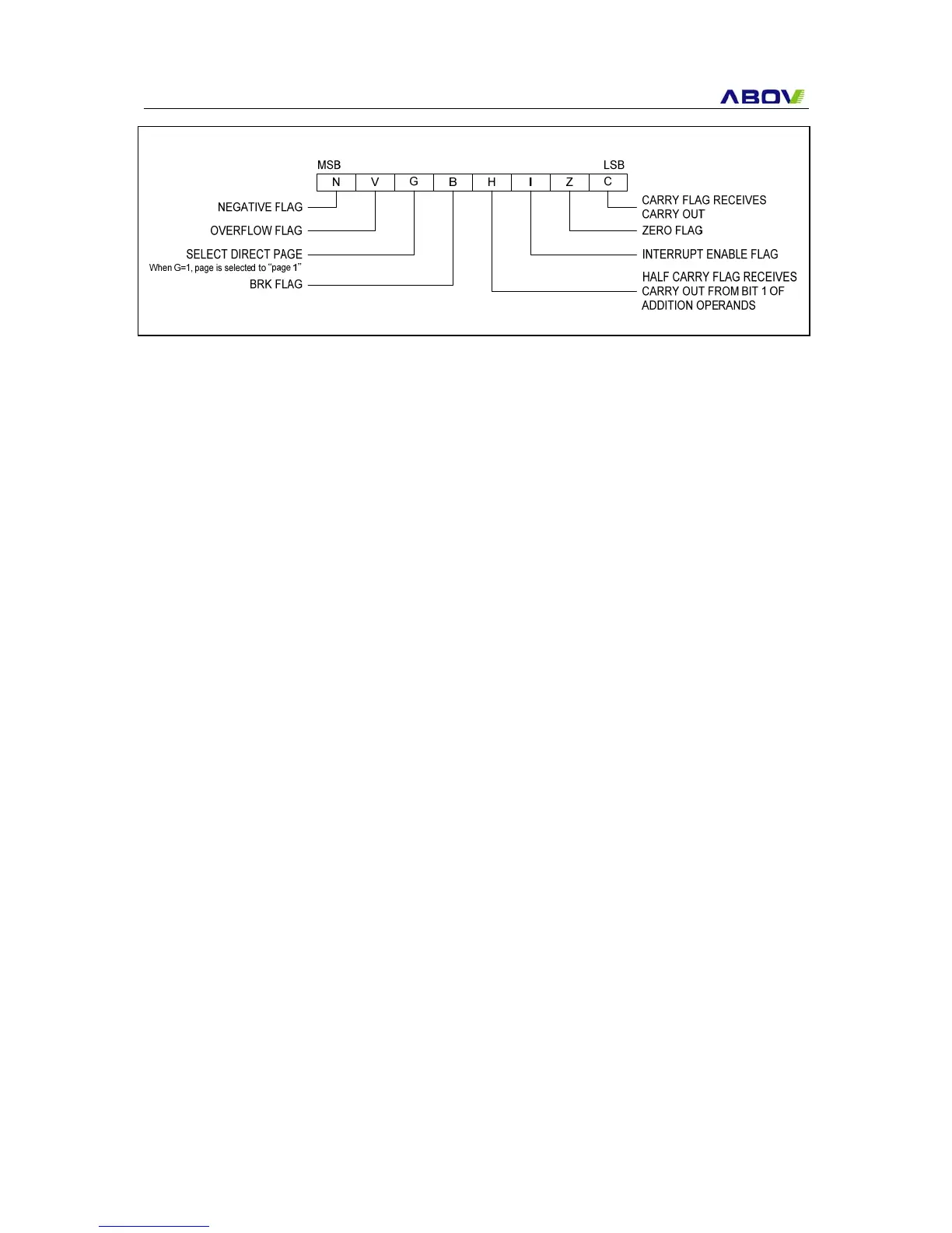
Program Status Word: Program Status Word (PSW)contains several bits that reflect the current
state of the CPU. It contains the Negative flag, the Overflow flag, the Break flag the Half Carry (for
BCD operation), the Interrupt enable flag, the Zero flag, and the Carry flag.
[Carry flag C]
This flag stores any carry or borrow from the ALU of CPU after an arithmetic operation and is also
changed by the Shift Instruction or Rotate Instruction.
[Zero flag Z]
This flag is set when the result of an arithmetic operation or data transfer is “0” and is cleared by any
other result.
[Interrupt disable flag I]
This flag enables/disables all interrupts except interrupt caused by Reset or software BRK instruction.
All interrupts are disabled when cleared to “0”. This flag immediately becomes “0” when an interrupt is
served. It is set by the EI instruction and cleared by the DI instruction.
[Half carry flag H]
After operation, this is set when there is a carry from bit 3 of ALU or there is no borrow from bit 4 of
ALU. This bit can not be set or cleared except CLRV instruction with Overflow flag (V).
[Break flag B]
This flag is set by software BRK instruction to distinguish BRK from TCALL instruction with the same
vector address.
[Direct page flag G]
This flag assigns RAM page for direct addressing mode. In the direct addressing mode, addressing
area is from zero page 00H to 0FFH when this flag is "0". If it is set to "1", addressing area is assigned
100H to 1FFH. It is set by SETG instruction and cleared by CLRG.
[Overflow flag V]
This flag is set to “1” when an overflow occurs as the result of an arithmetic operation involving signs.
An overflow occurs when the result of an addition or subtraction exceeds +127(7FH) or -128(80H).
The CLRV instruction clears the overflow flag. There is no set instruction. When the BIT instruction is
executed, bit 6 of memory is copied to this flag.
[Negative flag N]
Figure 9-5 PSW ( Program Status Word ) Registers