!"##"$"%"&%*""#
XM_unity_Installation&Maintenance_Manual Ed.1.3c2013 Page ;Aof (()
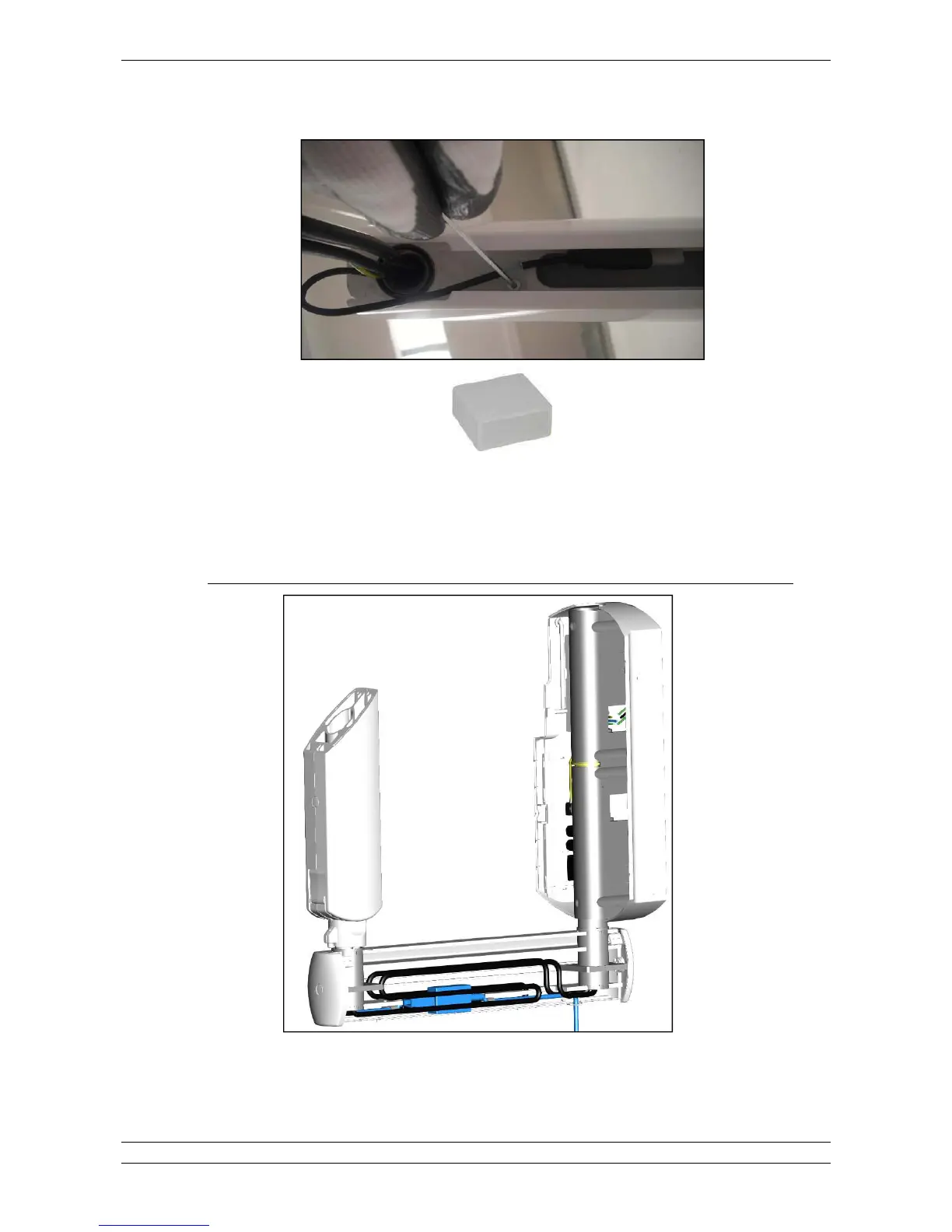
2. Fix the USB cable using the cable ties provided in the bracket (the USB connector is protected by a plastic cap as shown
below).
Fig.5.21
3. Route the COMM. CABLE in the bracket.
4. Route the POWER CABLE in the bracket.
When installing"80"&F%$.;)&*D(@?E$0B)&*D5(?EG-#%"!%0$%&"8#%!%6&%!!!/%3%80"&F%"!!3$18%#$1+
Fig. 5.22