System Operation
42 Adept Cobra i600/i800 Robot User’s Guide, Rev G
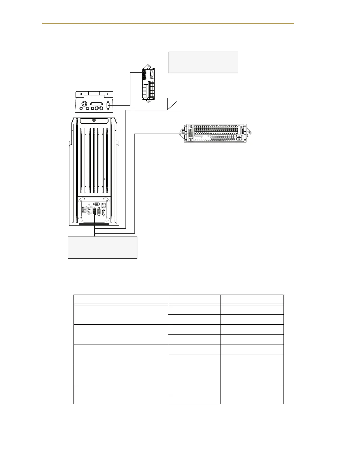
Figure 4-4 Connecting Digital I/O to the System
Table 4-4. Default Digital I/O Signal Configuration, Single Robot System
Location Type Signal Range
Robot 1 XIO connector Inputs 1001 - 1012
Outputs 0001 - 0008
IO Blox 1 Inputs 1033 - 1044
Outputs 0033 - 0040
IO Blox 2 Inputs 1041 - 1048
Outputs 0041 - 0048
IO Blox 3 Inputs 1049 - 1056
Outputs 0049 - 0056
IO Blox 4 Inputs 1057 - 1064
Outputs 0057 - 0064
GND
XSLV
1
2
SmartServo
RS-232
XPANEL
AC INPUT
(200-240VAC 1&)
+24V
DC INPUT
(24 VDC)
XIO
Cobra i600/i800 Robot
XIO Connector
12 Input signals: 1001 to 1012
8 Output signals: 0001 to 0008
IO Blox #1
8 Input signals: 1033 to 1040
8 Output signals: 0033 to 0040
Adept XIO Termination Block
XIO Breakout Cable
IO Blox Device

 Loading...
