Front Panel
Adept Cobra i600/i800 Robot User’s Guide, Rev G 49
4.7 Connecting Customer-Supplied Safety and Power Control
Equipment
Connecting Equipment to the System
The connection of the customer-supplied safety and power control equipment to the
system is done through the XUSR and XFP connectors on the AIB XPANEL cable. Refer to
Table 4-9 for the XUSR pin-out explanations. Refer to Table 4-10 on page 50 for the XFP
pin-out explanations. See Figure 4-8 on page 52 for the E-Stop wiring diagram.
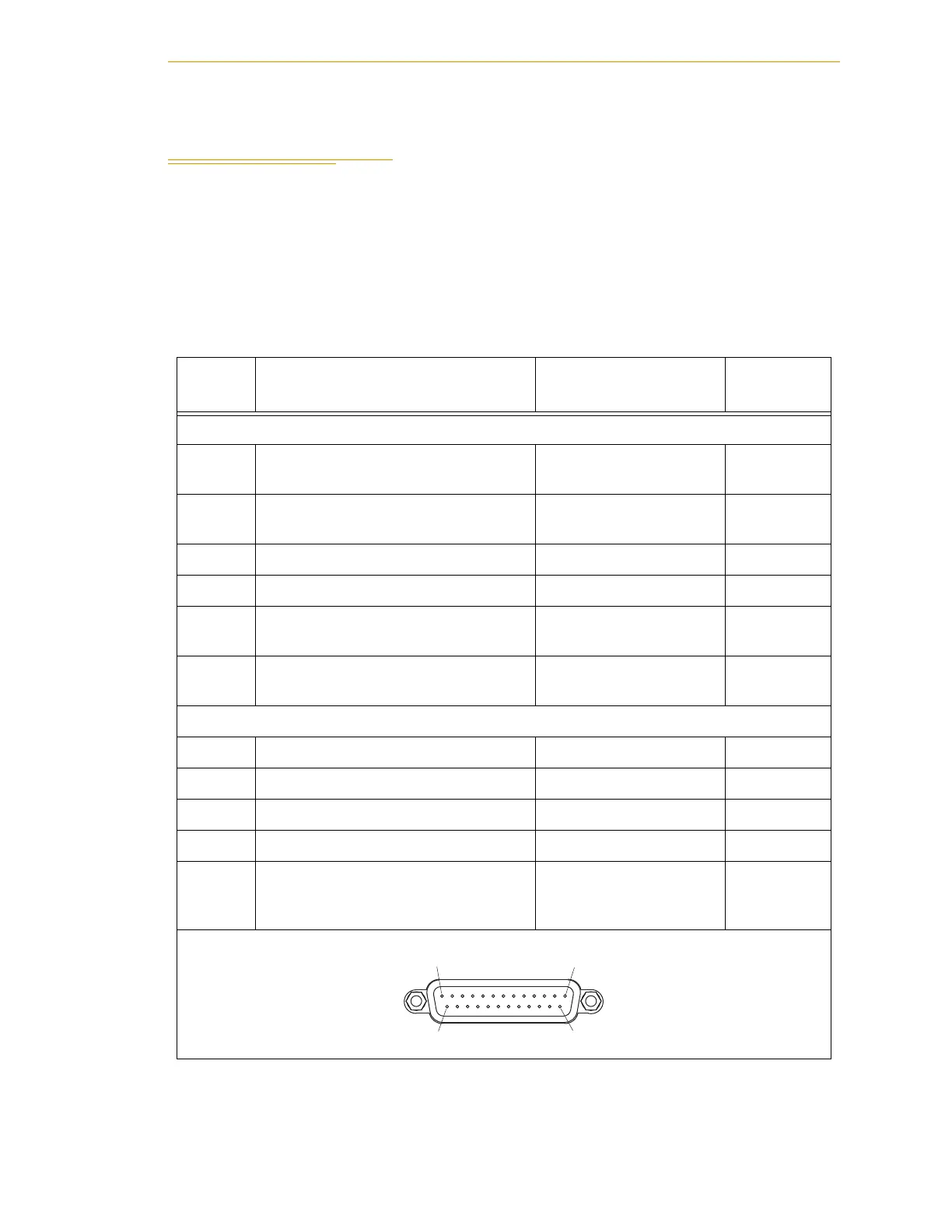
Table 4-9. Contacts Provided by the XUSR Connector
Pin
Pairs
Description Comments
Shorted if
NOT Used
Voltage-Free Contacts Provided by Customer
1, 14
User E-Stop CH 1 (mushroom PB,
safety gates, etc.).
N/C contacts
Ye s
2,15
User E-Stop CH 2 (same as pins 1
and 14).
N/C contacts
Ye s
3,16 Not supported on Cobra i-series robot
4,17 Not supported on Cobra i-series robot
5,18
Muted Safety Gate CH 1 (causes
E-Stop in AUTOMATIC mode only).
N/C contacts
Ye s
6,19
Muted Safety Gate CH 2 (same as
pins 5 and 18).
N/C contacts
Ye s
Voltage-Free Contacts provided by Adept
7,20 Not supported on Cobra i-series robot
8,21 Not supported on Cobra i-series robot
9,22 Not supported on Cobra i-series robot
10,23 Not supported on Cobra i-series robot
11,12,
13, 24,
25
No connection
XUSR
Pin 1Pin 13
Pin 14Pin 25

 Loading...
