System Operation
50 Adept Cobra i600/i800 Robot User’s Guide, Rev G
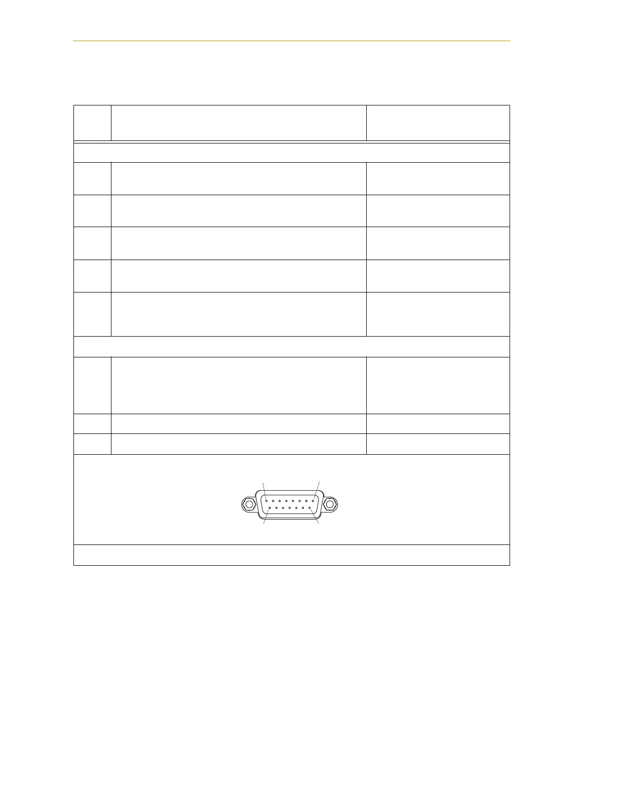
Table 4-10. Contacts Provided by the XFP Connector
Pin
Pairs
Description
Requirements for
User-Supplied Front Panel
Voltage-Free Contacts Provided by Customer
1,9
Front Panel E-Stop CH 1 (N/C contacts) User must supply N/C
contacts.
2,10
Front Panel E-Stop CH 2 (N/C contacts) User must supply N/C
contacts.
3,11
Remote MANUAL/AUTOMATIC switch CH 1. MANUAL
= Open AUTOMATIC = Closed
Optional - jumper closed for
Auto Mode only operation.
4,12
Remote MANUAL/AUTOMATIC switch CH 2. MANUAL
= Open AUTOMATIC = Closed
Optional - jumper closed for
Auto-Mode-only operation.
6,14
Remote High Power On/Off momentary PB User must supply momentary
push button to enable High
Power to system.
Nonvoltage-Free Contacts
5,13
a
a
Users must exercise caution to avoid inadvertently connecting 24 V signals to these pins,
because this will damage the electronics.
Adept Supplied 5 VDC and GND for High Power
On/Off Switch Lamp
User must supply lamp, or
use 1/4 W, 220 Ohm resistor.
System will not operate if not
present.
7,15
a
System 5 V power ON LED, 5 V, 20 mA Optional - indicator only
8 No connection
See Figure 4-9 on page 53 for a schematic diagram of the Adept Front Panel.
Pin 1
Pin 8
Pin 9
Pin 15
XFP
 Loading...

