Optional Equipment Installation
74 Adept Cobra i600/i800 Robot User’s Guide, Rev G
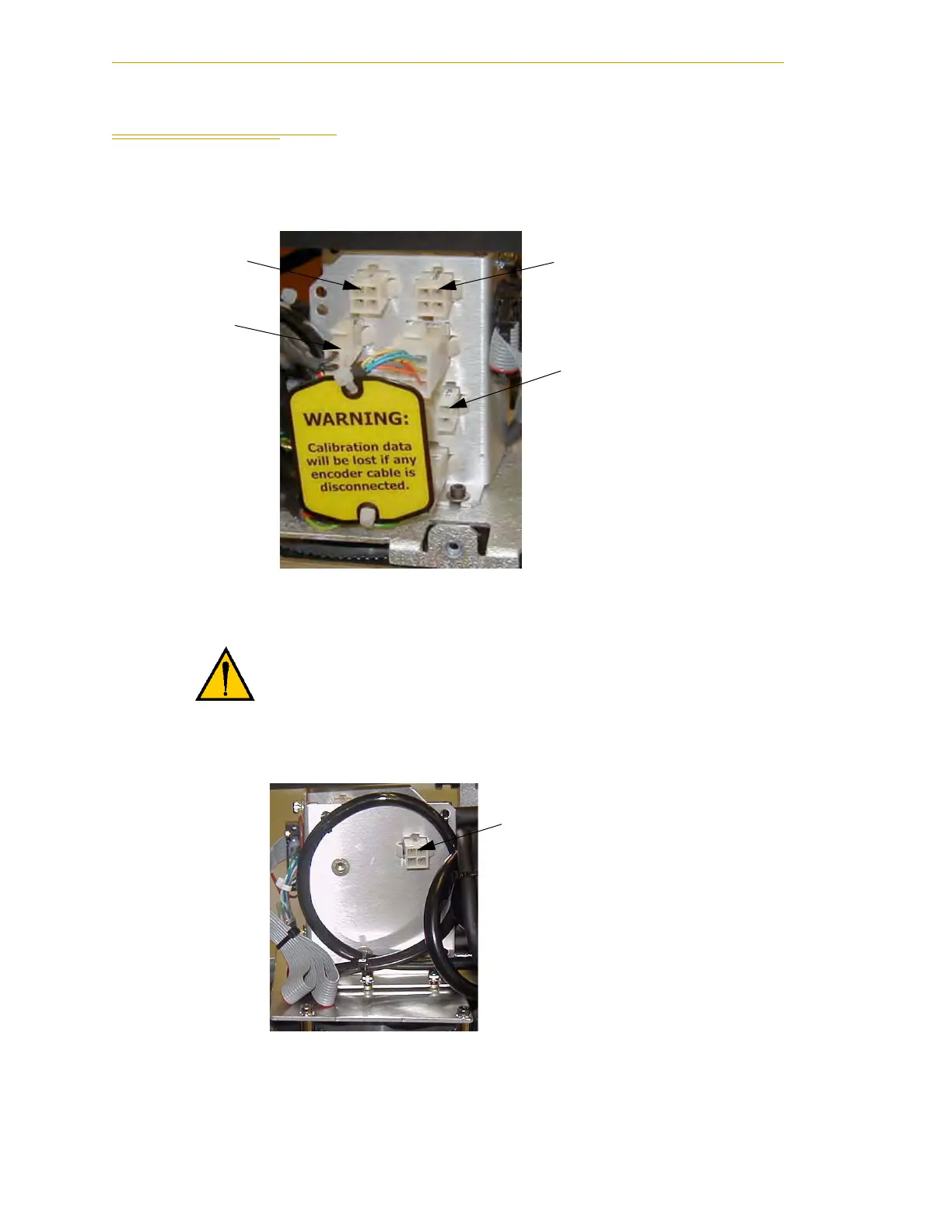
6.4 Internal User Connectors
The internal user connectors, OP3/4, EOAPWR, and ESTOP, can be accessed with the
outer link cover removed - see Figure 6-4. The SOLND connector is located on the
opposite side of the bulkhead area - see Figure 6-5.
Figure 6-4. Internal User Connectors - OP3/4, EOAPWR, ESTOP
Figure 6-5. SOLND Connector
WARNING: When the outer link cover is removed, you see
the label shown above. Do not remove the J3-ENC or
J4-ENC encoder cable connectors from their sockets. If
they are removed, the calibration data will be lost and the
robot must be run through a factory recalibration process,
which requires special software and tools.
NOTE: On early Cobra i600
robots, the J3-BRK and
ESTOP connectors are in
opposite locations from those
shown in the photo. Verify the
function by inspecting the
label on the socket.
EOAPWR
ESTOP
OP3/4
J3-BRK

 Loading...
