Optional Equipment Installation
76 Adept Cobra i600/i800 Robot User’s Guide, Rev G
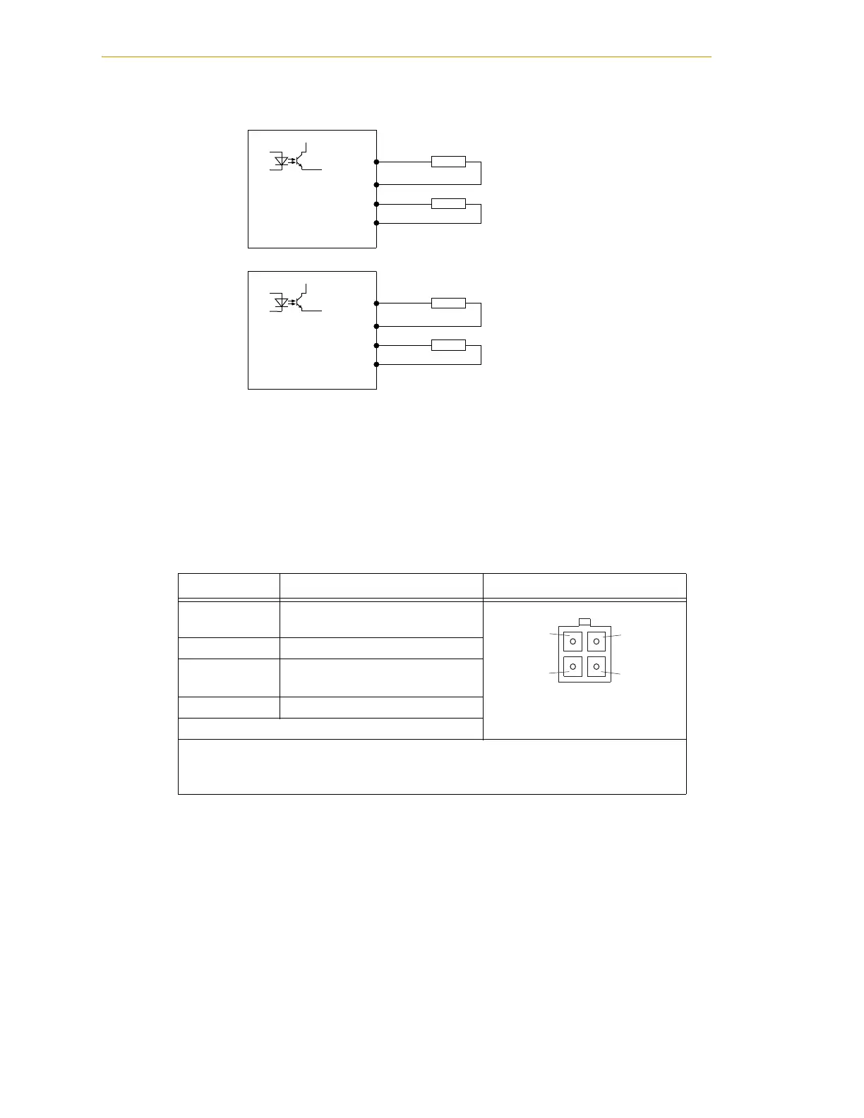
Figure 6-6. OP3/4 and SOLND Circuits
EOAPWR Connector
This 4-pin connector (see Figure 6-4 on page 74) provides 24 VDC power and ground for
user applications. See the following table for the pinouts and Table 6-4 for the output
specifications.
Table 6-3. EOAPWR Connector Pinout
Pin # Description Pin Location
1
24 VDC (see Table 6-4 for
current specs)
EOAPWR Connector
as viewed on robot
2Ground
3
24 VDC (see Table 6-4 for
current specs)
4Ground
Mating Connector:
AMP/Tyco #172167-1, 4-pin Mini-Universal Mate-N-Lok
AMP/Tyco #770985-1, Pin Contact, Mini-Univ. Mate-N-Lok
Pin 1
Pin 2
Pin 3
Pin 4
For optional second set of solenoids, or
other user-supplied devices.
Pin 1
Pin 2
Pin 3
Pin 4
For optional Robot Solenoid Kit installation, or
other user-supplied devices.
+24VDC
OP3/4 Connector Circuit
Signal 0011
GND
Signal 0012
GND
Load
Load
(equivalent
circuit)
+24VDC
SOLND Connector Circuit
Signal 0009
GND
Signal 0010
GND
Load
Load
(equivalent
circuit)

 Loading...
