User Connections on the Robot
Adept Cobra i600/i800 Robot User’s Guide, Rev G 73
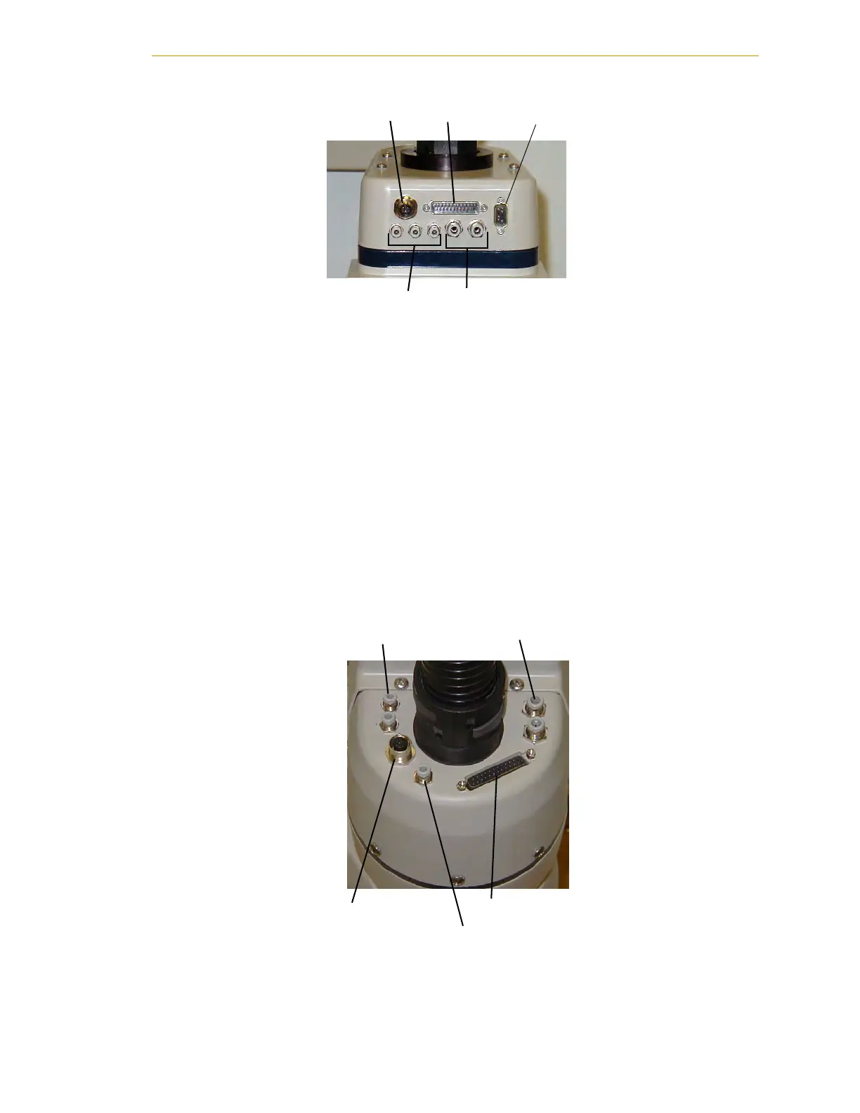
Figure 6-2. User Connectors on Joint 1
NOTE: See page 41 for information on the IO Blox connector. Also refer to
the Adept IO Blox User’s Guide for details.
User Electrical Lines
There is a 25-pin male connector (24 conductor) on the robot user panel on the back of
Joint 1 for user electrical lines (see Figure 6-2). This connector is wired directly to a 25-pin
female connector on the top of the outer link (see Figure 6-3). These connectors can be
used to run user electrical signals from the user panel, through the robot, and up to the
outer link.
Wire Specifications: Wire size: 0.1 mm
2
, Pin Numbers 1-24, 12 pairs, twisted in pairs as
1&2, 3&4, 5&6, ..., 23&24. Maximum current per line: 1 Amp.
Figure 6-3. User Connectors on Joint 2
4 mm Air Lines 6 mm Air Lines
DeviceNet User Electrical IO Blox
DeviceNet
4 mm Air Lines
6 mm Air Lines
User Electrical
4 mm Air Line

 Loading...
