Robot Installation
22 Adept Cobra i600/i800 Robot User’s Guide, Rev G
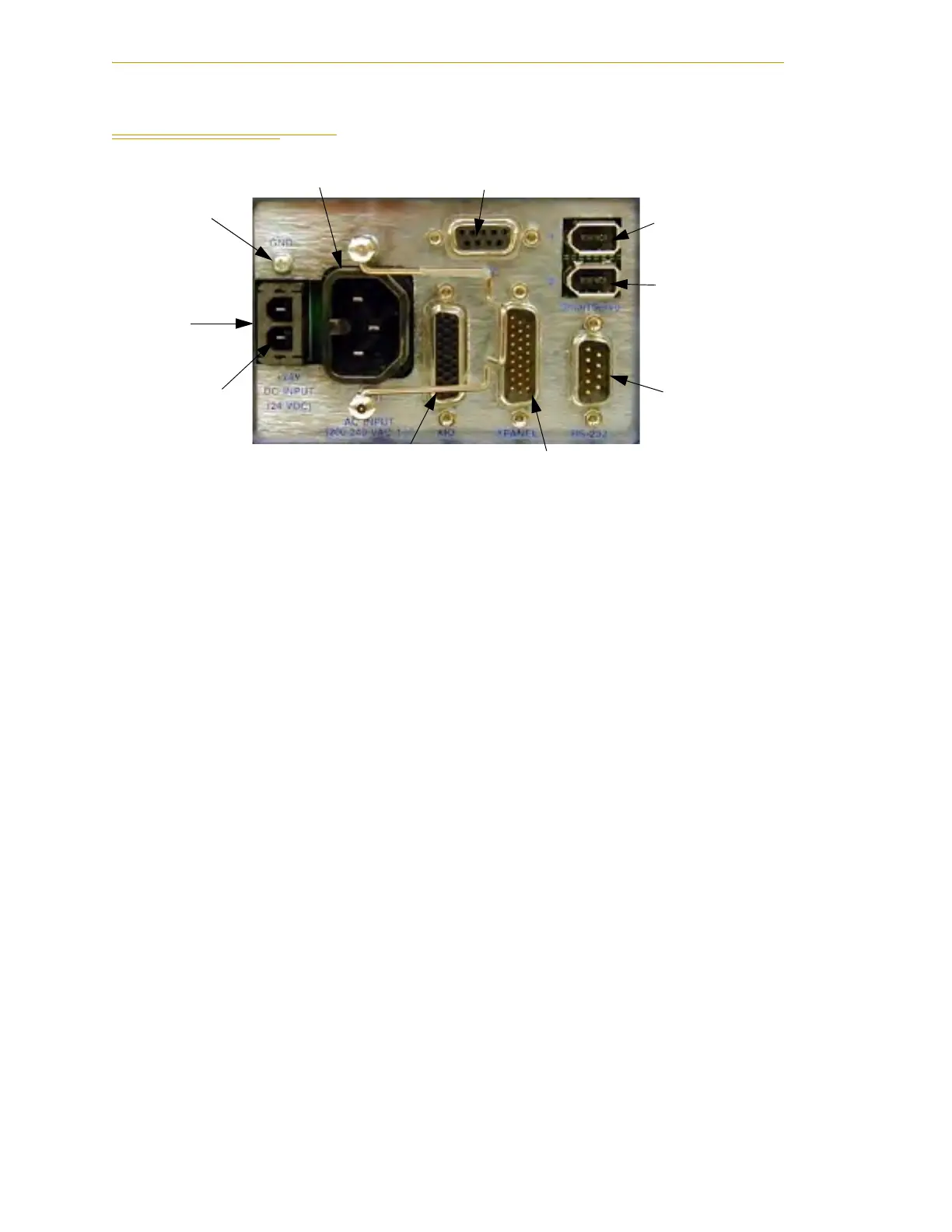
2.6 Connectors on the Robot Interface Panel
Figure 2-3. Robot Interface Panel
24 VDC - for connecting user-supplied 24 VDC power to the robot. The mating connector
is provided.
Ground Screw - for connecting cable shield from user-supplied 24 VDC cable.
200/240 VAC - for connecting 200-240 VAC, single-phase, input power to the robot. The
mating connector is provided.
XSLV - not used in a Cobra i600/i800 robot system.
SmartServo 1/2 - not used in a Cobra i600/i800 robot system.
RS-232 - for connecting a user-supplied computer, running Adept ACE software. (DB-9,
male).
XPANEL - for connecting the AIB XPANEL cable. The AIB XPANEL cable has connectors
for the Front Panel (XFP), T2 pendant (XMCP), and user IO (XUSR). (DB26, high density,
male).
XIO - for user I/O signals for peripheral devices. This connector provides 8 outputs and
12 inputs. See Section 4.6 on page 43 for connector pin allocations for inputs and outputs.
That section also contains details on how to access these I/O signals via MicroV+. (DB26,
high density, female). The optional XIO Termination Block connects here. This device
provides a termination block for I/O connections, plus status LEDs and switches to test
I/O signals.
24 VDC
Input
200-240 VAC
XSLV
XIO
XPANEL
RS-232
SmartServo Port 1
+24 VDC
Pin
Ground
Screw
SmartServo Port 2

 Loading...
