Optional Equipment Installation
82 Adept Cobra i600/i800 Robot User’s Guide, Rev G
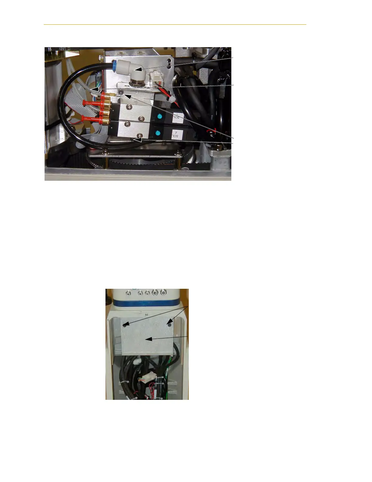
Figure 6-10. Solenoid Placement Using Mounting Hardware
9. Install the appropriate lengths of 4 mm (5/32 in.) plastic tubing (supplied) into
the two output ports on the manifold. Route the tubing up along the tower
bracket next to the quill and down through the center of the quill. Use cable ties,
as needed, to secure the tubing.
10. Loosen the securing screw on the AIB chassis, and lower the chassis down flat.
See Figure 5-2 on page 65 for the location of the securing screw.
11. Remove the cable strap plate by removing two screws and split washers. See
Figure 6-11. This allows the harness to move when you lift the J1 cover in the next
step.
Figure 6-11. Removing the Cable Strap Plate
12. Remove the four screws for the Joint 1 cover and lift the cover up so you have
access to the tubing under the cover. See Figure 6-12.
Air intake
coupling with
spare air line
Tubing connected
to output port
Mounting screws for
solenoid assembly
Two M5 x 8 screws
Cable Strap Plate

 Loading...
