Optional Equipment Installation
78 Adept Cobra i600/i800 Robot User’s Guide, Rev G
Figure 6-7. Internal E-Stop Connector Circuit
NOTE: This circuit will trigger an emergency stop of the local robot only.
It does not to link the E-Stop chain of the host system
Procedure to Enable Breakaway E-Stop Function
To enable the Breakaway E-Stop function, you have to use the Configuration Manager to
change the default configuration.
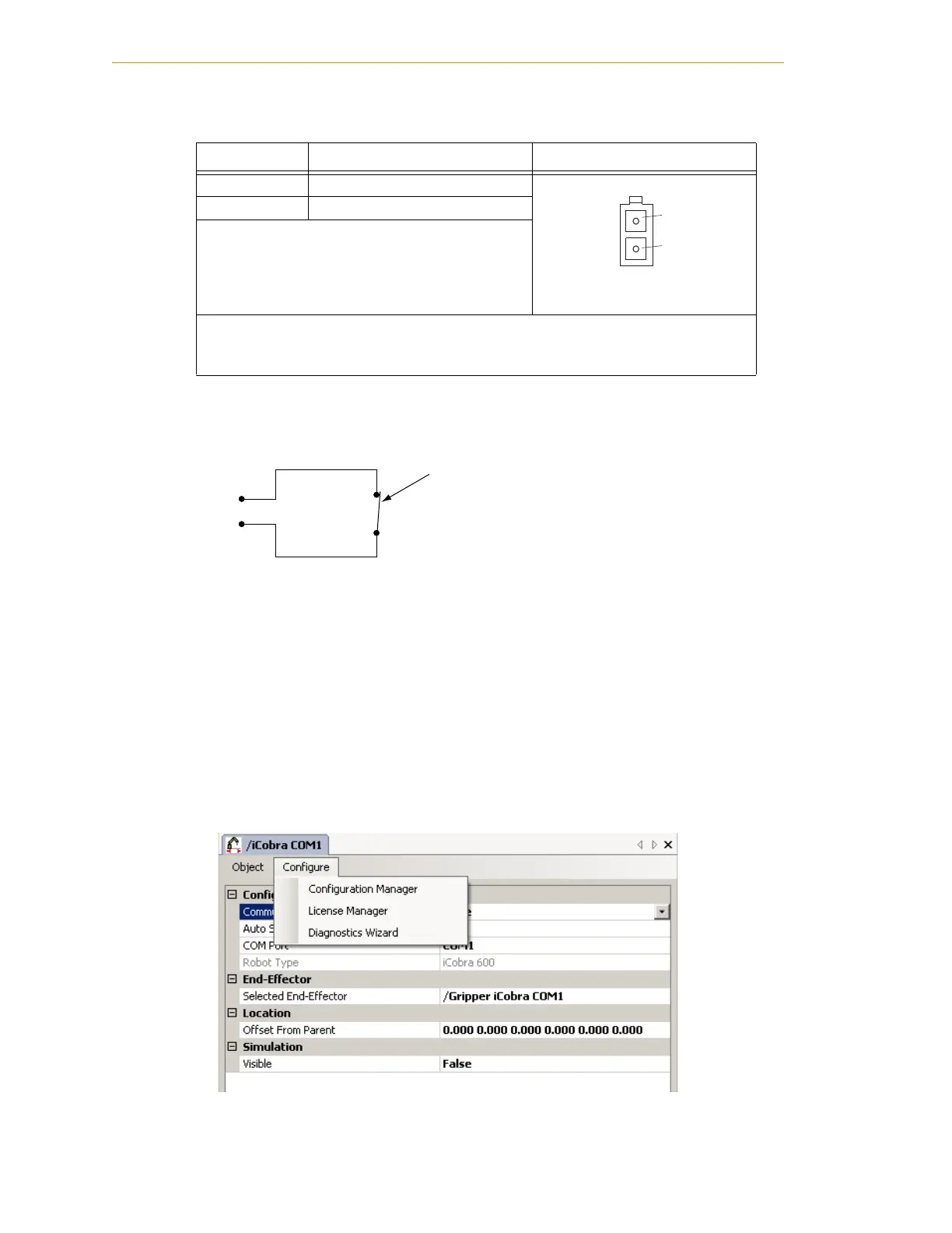
1. Double-click the iCobra object in the Folder pane of the Workspace Explorer.
2. In the object editor, select Configure > Configuration Manager. See the following
figure.
Figure 6-8. Selecting the Configuration Manager
Table 6-5. ESTOP Connector
Pin # Description Pin Location
1 ESTOP_INPUT
ESTOP Connector
as viewed on robot
224 V
Mating Connector:
AMP/Tyco #172165-1, 2-pin Mini-Universal Mate-N-Lock
AMP/Tyco #770985-1, Pin Contact, Mini-Univ. Mate-N-Lok
Pin 1
Pin 2
User-supplied normally-closed contact.
Can be connected to a break-away sensor
to cause an E-Stop condition when circuit
is open.
Note: This function is disabled by default - it must
be enabled in software.
Typical ESTOP
Connector Circuit

 Loading...
