1569‐PT060EE1 Rev.7 Page12of62
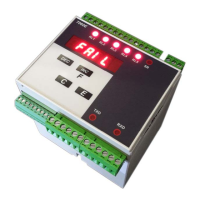
2.3.2 LED signals
ThemeaningofthemessagesprovidedbythesignalLEDSlocatedontheinstrument’sfrontpanelisthefollowing:
RL1÷RL5 TheLEDisonduetothetriggeringoftherelativethreshold
SR TheLEDisontonotifythetriggeringofthesafetysignal
TX TheLEDflashestosignalthetransmissionactivityofserialport1.
RX TheLEDflashestosignalthereceivingactivityofserialport1.
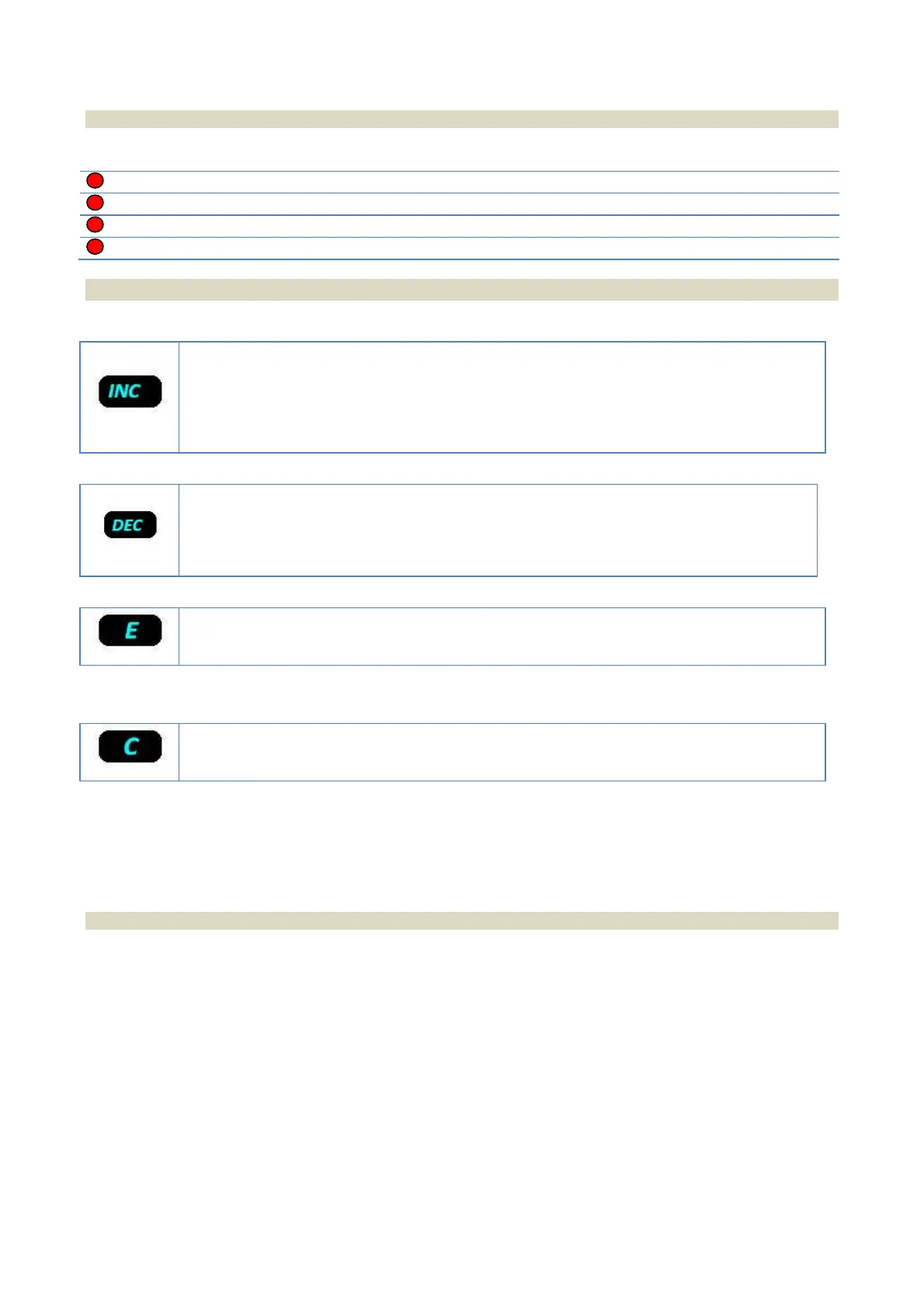
2.3.3 Key functions
Iftheinstrumentisinoperatingmode,itallowscommutingthereading(iftheinstrumentforesees
the optional second channel) to display the weight value of the second channel or total value
(channel1+channel2).
Iftheinstrumentisinconfigurationmode,itallowsbrowsingforwardthemenuitemsand
increasingtheparameters’value.
If the instrument is in operating mode and the weight was zeroed, the display will indicate the
valuebypressingthiskey(fortheselectedchannel).
Iftheinstrumentisinconfigurationmode,itallowsbrowsingbackwardthemenuitemsand
decreasingtheparameters’value.
Iftheinstrumentisinoperatingmode,itallowsenteringinconfigurationmode.
Iftheinstrumentisinconfigurationmode,thekeywillconfirmtheselectionsmade.
Iftheinstrumentisinoperatingmode,ithasnofunction.
Iftheinstrumentisinconfigurationmode,thiskeywillcanceltheselectionsmade.
2.4 Self-troubleshooting
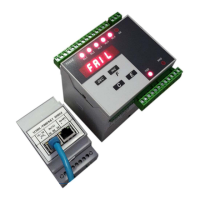
2.4.1 Cell connection fault (FAIL)
Theinstrumentconstantlychecks the correctconnectionof theload cell(interruption and short‐circuitof the signal
andpowersupplyconnections)and,incaseananomalyisdetected,aFAILinternalsignalisgenerated.
ByprogrammingoneormorerelaysasFAIL,inadditiontothemessageappearingon
thedisplay,allchannel’srelays
are forced in alarm status (they are de‐energized). For example, by programming FAIL 1, all relays set with alarm
thresholdsonchannel1and/orthetotal,areforcedinalarmstatus.
 Loading...