1569‐PT060EE1 Rev.7 Page17of62
3.7 Connection of load cells (side A)
Thecablecomingfrom the loadcells orjunction boxmust beconnectedto theterminals locatedonthe rear ofthe
instrumentandcalledLOADCELL1.
Connection between the load cell and the instrument must be carried out with
a shielded cable. The cable’s shield
mustbeconnectedtotheground.
Connectionmusttakeplacerespectingthecolourcodeindicatedontheloadcells.
T060 foresees the standard connection of 6‐wire load cells.In case of connection of 4‐wire load cells, connect the
referencewirestotherelative
polaritiesofthepowersupplycables.
MAKESURETHECONNECTIONCABLEBETWEENLOADCELLSANDINSTRUMENTISDUCTEDINTROUGHSSEPARATE
FROM THOSE OF POWER LINES, IN ORDER TO AVOID COUPLING THAT MAY PREJUDICE THE MEASUREMENT
ACCURACY.
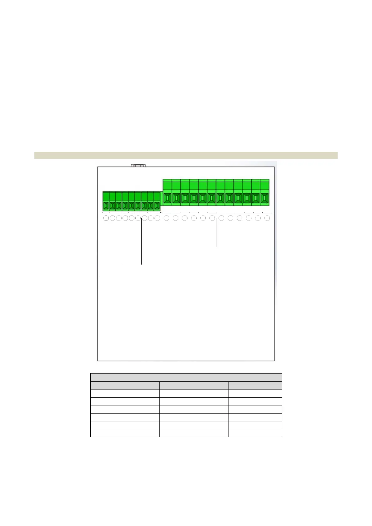
3.7.1 Connection of load cells 1
LC1
INDICATION FUNCTION TERMINAL
+A +Excitation 39
‐A ‐ Excitation 38
+S +Signal 37
‐S ‐ Signal 36
+R +Reference 35
‐R ‐ Reference 34
3128 29 30
-S
+R
-R
3432 33
+S
3635 37
-A
+A
3938
-R
+R
-S
+S
-A
+A
LOAD CELL 2 LOAD CELL 1
232019 2221 2524 2726
SGND 3
IOUT+
VOUT+
SGND 2
-RS485
+RS485
SGND 1
-RS485/RX
+RS485/TX
SERIAL
OUT 1
SERIAL
OUT 2
ANALOG
OUTPUT
OPTO OPTO
 Loading...