1569‐PT060EE1 Rev.7 Page14of62
3. INSTALLATION
3.1 Receiving the material
Beforesigningthetransportdocument,makesuretherearenodamagestotheequipmentcausedduringtransport
andifso,notifythecarrier.
Inadditiontotheinstrument,thefollowingmustbepresent:
1seriesoffemaleflyingterminalsforconnectingthepowersupplyandinputandoutput
signals
1copyoftheinstructionmanual
1 copy of the instrument’s testing report (check that the serial number appearing in the relative label
correspondstotheserialnumberindicatedonthetestingsheet).
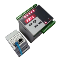
INPUT100‐240V~
10W50/60Hz
MODELT060E1
S.N.20160234
Eachdevicefeaturestherequiredinformationforproperidentification:modelandserialnumber.
Thisdata,togetherwiththesoftwareversion,mustbeindicatedwhenrequestinginformation.
3.2 Assembling the instrument
WARNING
Makesurethatthesupplyvoltagefallswithintheinstrument’sallowedlimits.
Makesurethatitispossibletodisconnectpowerduringinstallationand/ormaintenancephases.
Performagroundconnectionifrequired.
Itisrecommendedtouseashieldedcableforcell’sinputsignals,analogueoutputsandseriallines.
Use
troughsforcell’sinputsignals,analogueoutputsandseriallines,whichareseparatefromthoseofpowersignals.
Connectthepanelonwhichtheinstrumentisinstalledtotheground.
Theinstrument’soutputrelaysmustbeusedtocontroltherelays’coils(whichnominalcurrentmustfallwithin
declaredlimitsand
anyhow,usingsuitablearcsuppressiondevices),logicinputsorsignalLEDS;theymustnotcontrol
powersignals.
 Loading...