Configuration and Activation 4-23
value as AI_1 through AI_8 (at the monitor's sample interval).
Define analog outputs from a list of available data entities and
output the corresponding data value to an external analog device.
Note: The analog device is a custom configuration. Please
consult ADS prior to wiring and configuring this device.
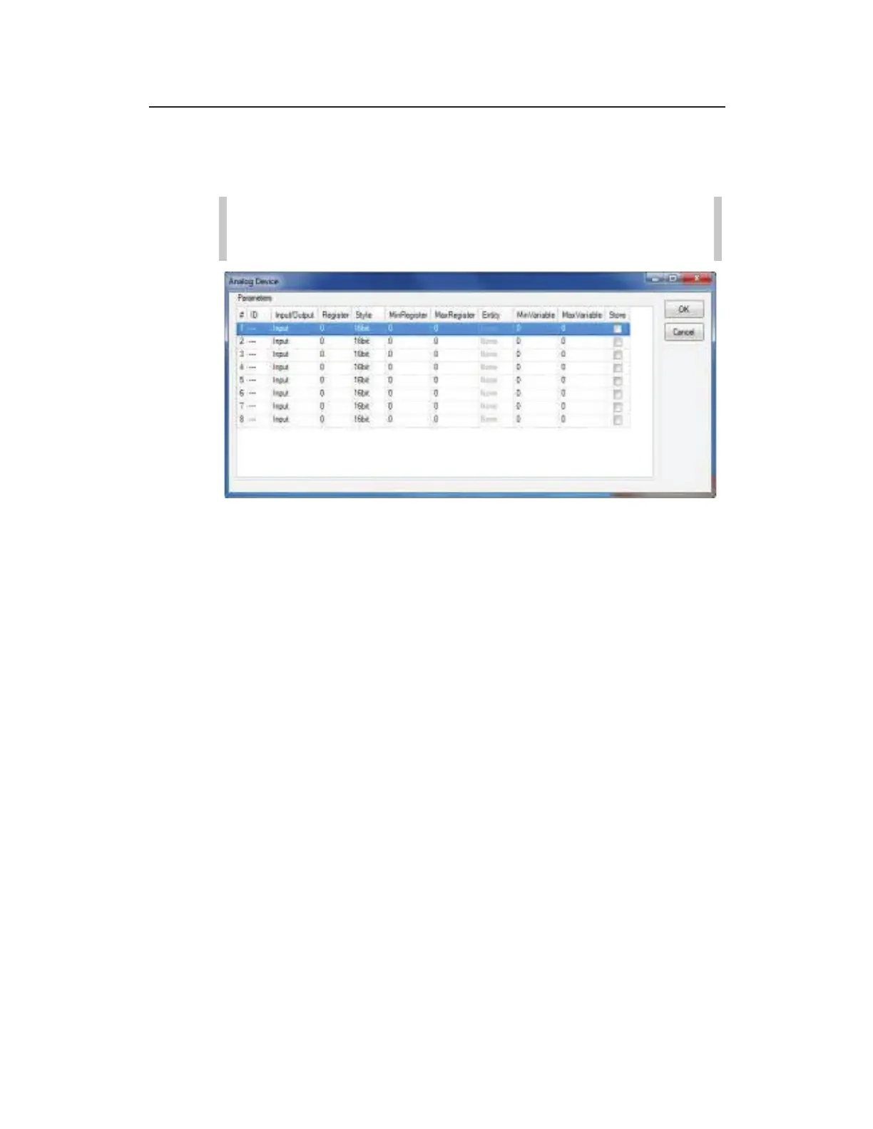
Analog Device properties dialog
Configure the analog device for a TRITON+ using the following
information:
z # Displays the channel number associated with the analog
input or output. Can be modified, if necessary.
z ID Input the Modbus identification corresponding to the
external analog Modbus module. This value is typically found
in the customer's external analog module's user guide.
z Input/Output Select whether the attached analog device is
for analog inputs or analog outputs.
z Register Enter the Modbus register corresponding to the
external analog Modbus module. This value is typically found
in the customer's external analog module's user guide.
z Style Choose the correct register size for your external analog
Modbus module.
z MinRegister Enter the minimum scaling values
corresponding to the external Modbus module. This value is
typically found in the customer’s external analog module’s
user guide.