Sensor Installation and Connection 5-57
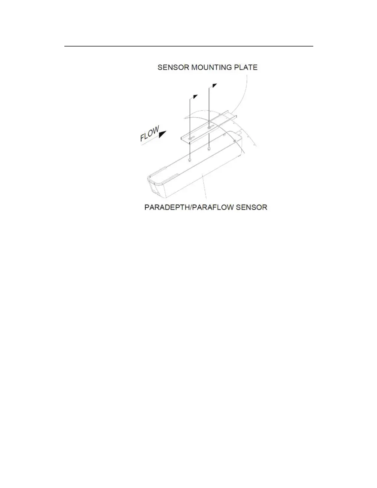
Fastening the downward looking sensor to the mounting plate on the band
12. Confirm the sensor is still level. For the ParaDepth or
ParaFlow sensor refer to Chapter 4 Running Sensor
Diagnostics for more information on determing how level the
sensor is. For the Surface Combo or Ultrasonic Depth sensor,
confirm level side to side and front to back as described on
Page 5-33. To protect the crystals on the sensor, use a block of
wood of uniform dimensions between the level and the flat face
of the horizontal, ultrasonic depth sensor portion of the sensor!
13. Determine the Physical Offset for the Surface Combo sensor
or Ultrasonic Depth sensor by measuring the distance from the
crown (top) of the pipe to the face of the sensor (horizontal
surface with the two ultrasonic crystals on either sensor). This
value is required when configuring the monitor using the
Qstart
XML
software. Do not measure in reference to the the
angled surface velocity or surcharge velocity portions of the
sensor.