1 NVR Overview
1.3 Alarm Connections
1.3.1 Alarm Port
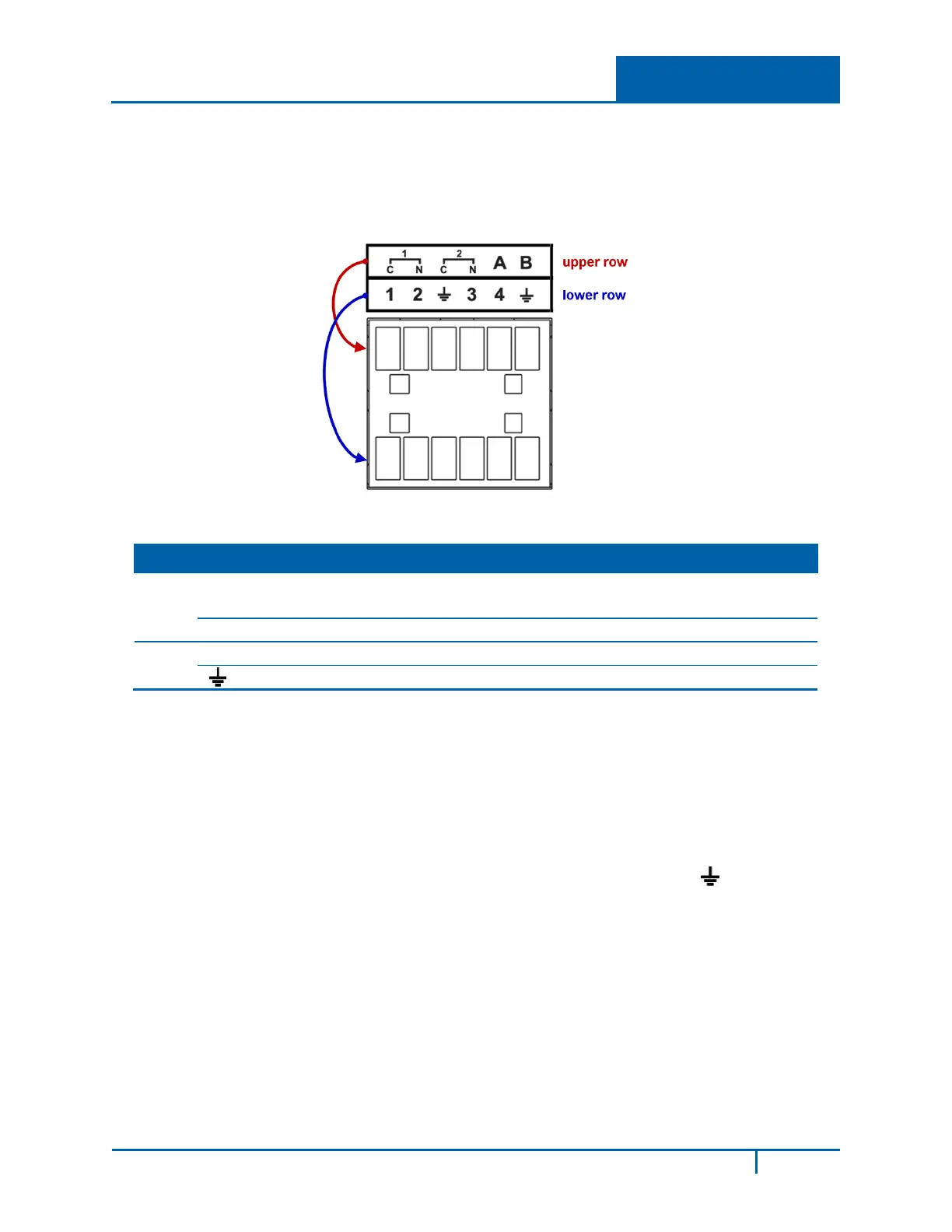
Please refer to the following figure for detailed information about the alarm port.
Figure 1-4
Row ID Description
Upper N1/C1
N2/C2
Alarm Output groups 1–2
N is a normally open alarm output port and C is the alarm output common.
A/B 485 communication port: controls the PTZ decoder
Lower 1–4 Alarm Inputs NO (normally open)
Ground
Note: When your alarm input device is using external power, make sure the device and the NVR
have the same ground. Also, make sure that there is power to the external alarm device.
1.3.2 Alarm Input Port
To connect an alarm:
1. Connect the positive end (+) of the alarm input device to the alarm input port (1-4) of the NVR.
2. Connect the negative end (–) of the alarm input device to the ground end ( ) of the NVR.
In the example that follows, alarms 1 and 3 are configured.
NVR4200 Series User Guide
5
 Loading...