ADTECH9 Series CNC Maintenance Manual
- 183 -
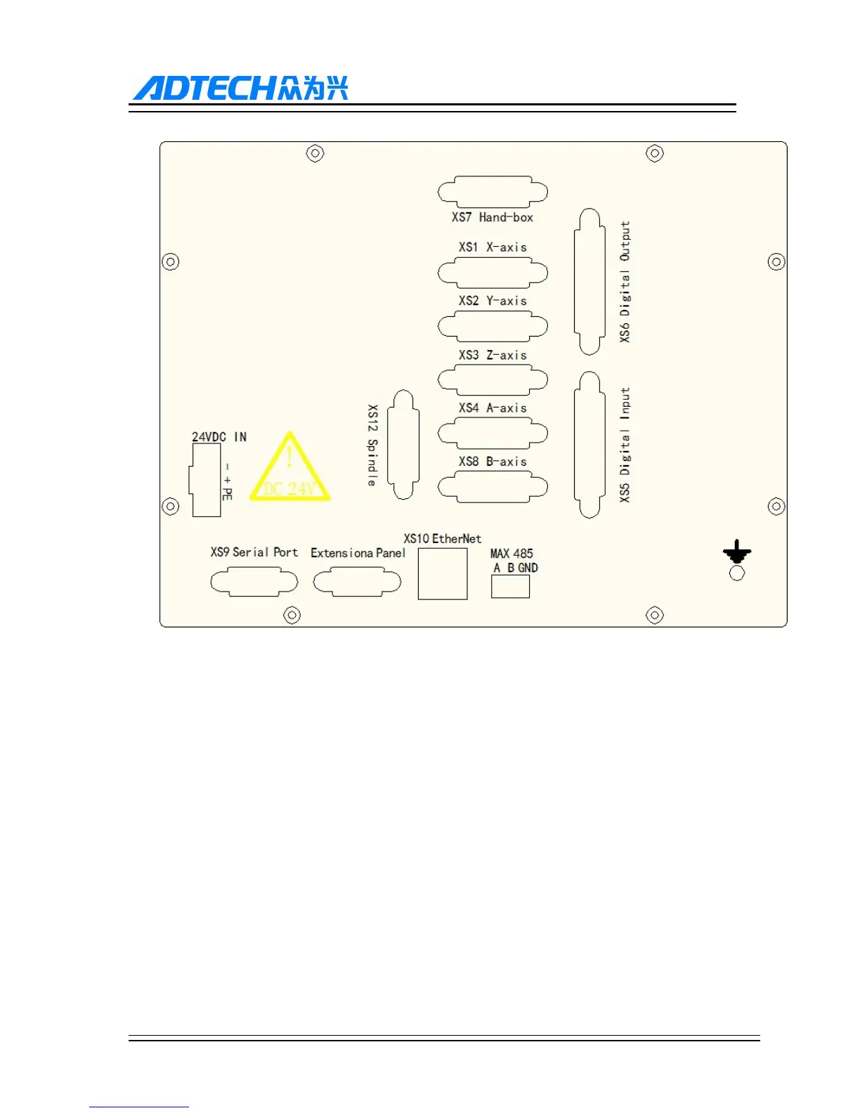
11.1.2. 9810 and 9650 series external interface diagram
XS1(X axis), XS2(Y axis), XS3(Z axis), XS4(A axis), (XS8 axis): 15-core D-pin socket connects to step motor
driver or digital AC servo driver.
(2) XS5 digital input: 25-core D-pin socket inputs signals for every axis limit and other switching quantity.
(3) XS6 digital output: 25-core D-pin socket outputs signals for switching quantity.
(4) XS9 serial port exchange files between PC and CNC96 controller and realize other functions.
(5) CNC98 controller uses 24V DC power supply, and the internal power consumption is about 5W.
(6) XS7 extensional panel: 15-core D-pin socket connects to hand wheel
(7) XS8 Spindle: 26-core D-pin socket connects to spindle inverter or servo host driver.