ADTECH9 Series CNC Maintenance Manual
- 227 -
12.
CNC9 Series Hardware Interface Instructions
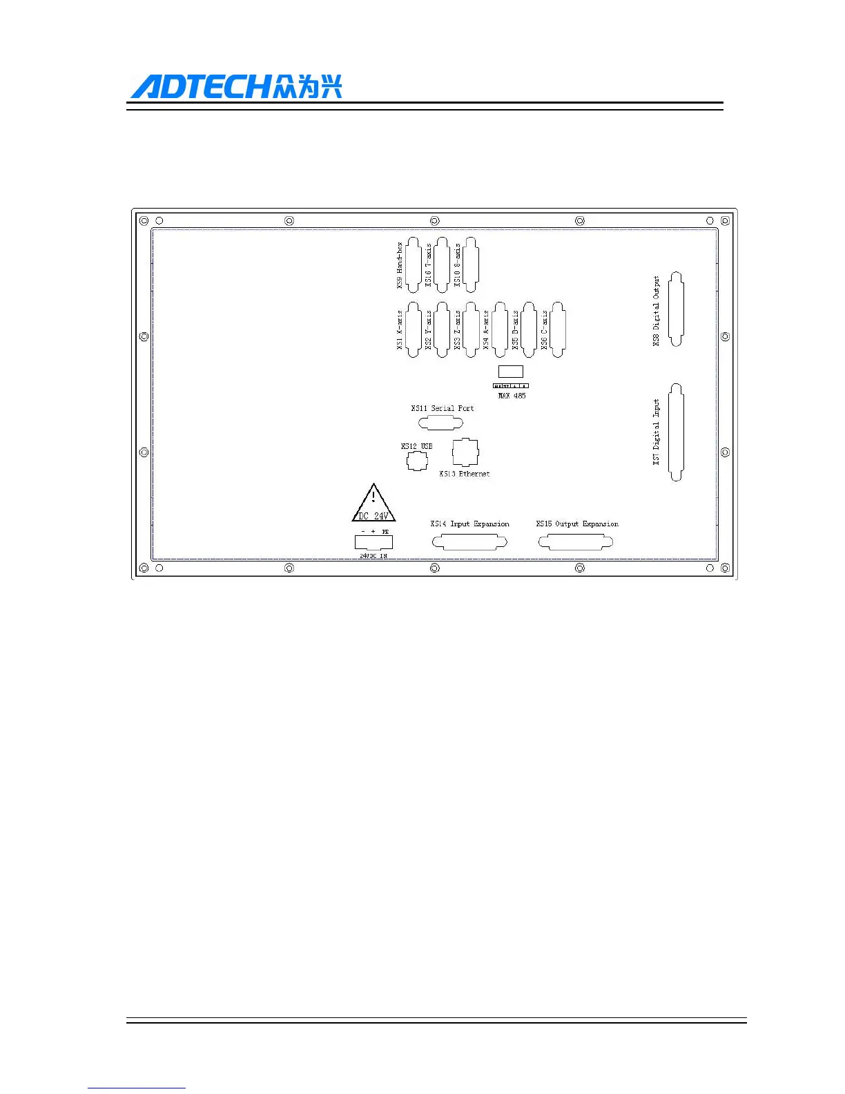
12.1. External Interface Diagram
XS1 (X axis), XS2 (Y axis), XS3 (Z axis), XS4 (A axis), XS5 (B axis), XS6(C axis), XS16(7 axis), XS10(8 axis):
15-core D-pin socket connects to step motor driver or digital AC servo driver.
(2) XS7 machine tool input interface: 37-core D-pin socket inputs signals for every axis limit and other
switching quantity.
(3) XS8 machine tool output interface: 25-core D-pin socket outputs signals for switching quantity.
(4) USB and serial port exchange files between PC and CNC99 controller and realize other functions.
(5) CNC99 controller uses 24V DC power supply, and the internal power consumption is about 5W.
(6) XS9 hand wheel interface: 15-core D-pin socket connects to hand wheel
(7) XS14 machine tool extended input interface: 25-pin D-type socket is switching quantity extended input
signal
(8) XS15 machine tool extended output interface: 25-pin D-type socket is switching quantity extended output
signal
12.2. Motor driver control interface
The definitions of XS1…XS4 XS5 XS6 (corresponding to X axis, Y axis, Z axis, A axis, B axis, C axis) are as
follows: