ADTECH9 Series CNC Maintenance Manual
- 208 -
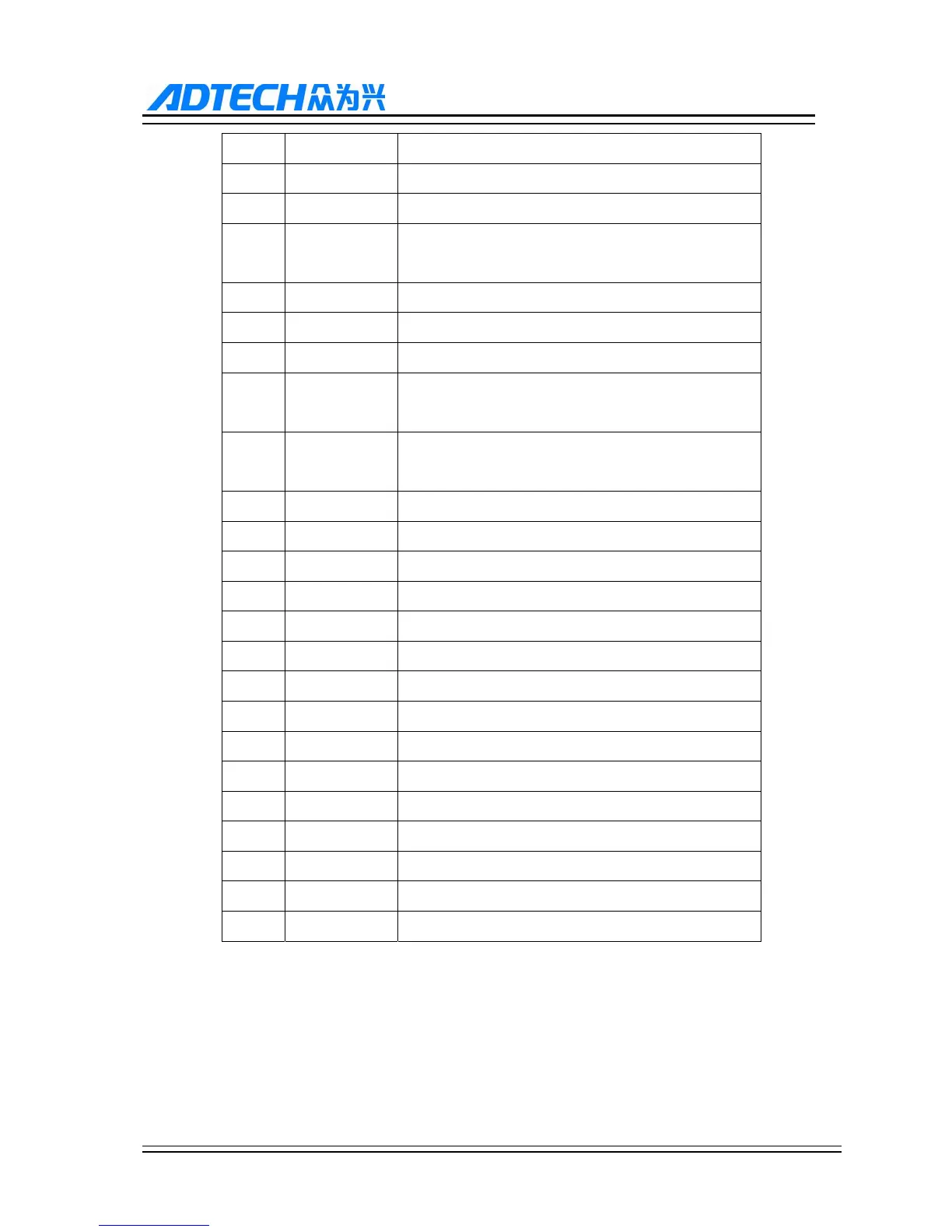
3 UECB- Spindle encoder B-
4 UECA+ Spindle encoder A+
5 EXT_GNDA Spindle encoder power GND
6 EXTVCC5.0V Spindle encoder 5V+ (supply 5.0V voltage to external,
250MA)
7 CDR- Spindle position control direction -(DR-) PU+
8 CDR+ Spindle position control direction +(DR+) PU-
9 CPU- Spindle position control pulse -(PU-) DR-
10 AXIS_IN1 Spindle alarm input port 1 (IN93 needs EXT_INCOM5
to connect 24V voltage)
11 AXIS_IN2 Spindle alarm input port 2 (IN94 needs EXT_INCOM5
to connect 24V voltage)
12 UECZ+ Spindle encoder Z+ (9810 9650: IN77, 9960: IN78)
13 UEB+ Spindle encoder B+
14 UECA- Spindle encoder A-
15 AXES2 Spindle output port 2(CCW)(OUT55)
16 AXES4 Spindle output port 4 (OUT57)
17 AXES6 Spindle output port 6 (OUT59)
18 CPU+ Spindle position control pulse +(PU+) DR-
19 PWM1 PWM output
20 DAOUT2 Second channel analog output 0~10V
21 DAOUT1 First channel analog output 0~10V
22 DAGND Analog GND
23 AXES1 Spindle output port 1(CW)(OUT54)
24 AXES3 Spindle output port 3 (OUT56)
25 AXES5 Spindle output port 5 (OUT58)
26 24VGND Control signal common terminal power 24V GND
AB phase decoder input allows differential connection and common anode connection, which is determined
by the encoder type.
Encoder output modes include open collector, complementary, voltage and line driver, among which open
collector, complementary and voltage outputs use common anode connection, and line driver output uses
differential connection.