ADAM-4000 Series User Manual 264
Analog input/output modules are calibrated when you receive them. However, cali-
bration is sometimes required. No screwdriver is necessary because calibration is
done in software. Calibration parameters are stored in the ADAM module’s onboard
EEPROM.
The ADAM modules come with utility software that supports the calibration of analog
input and analog output. Aside from the calibration that is carried out through soft-
ware, the modules incorporate automatic Zero Calibration and automatic Span Cali-
bration at boot-up or reset.
8.1 Analog Input Module Calibration
Models: ADAM-4011, 4011D, 4012, 4016, 4017, 4017+, 4018, 4018+, 4018M,
4019+
1. Set modules as initial mode before applying power to the module and let it warm
up for about 30 minutes
2. Assure that the module is correctly installed and is properly configured for the
input range that you want to calibrate. You can do this by using the ADAM utility
software. (Please refer to Appendix D, Utility Software.)
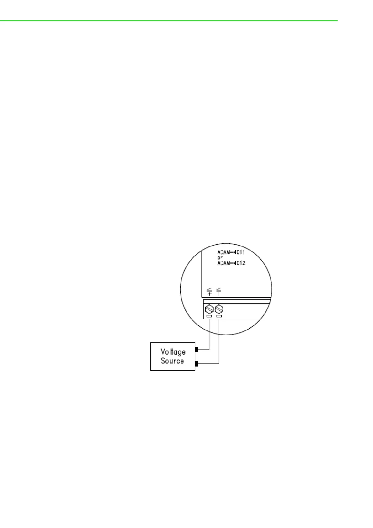
3. Use a precise voltage source to calibrate the module through +IN and -IN termi-
nals for ADAM-4011, 4011D and 4012. However, for ADAM-4016, the calibrat-
ing voltage should be applied to terminals Vin+ and Vin- (or Iin+ and Iin-). At
last, Vin0+ and Vin0- are used for calibration in ADAM-4017, 4017+, 4018,
4018+, 4018M, 4019 and 4019+ models.
Figure 8.1 Applying Calibration Voltage
 Loading...