275 ADAM-4000 Series User Manual
Chapter 8 Calibration
8.4 Analog Output Calibration
Model: ADAM-4021/4024
The output current of analog output modules can be calibrated by using a low and
high calibrating value. The analog output modules can be configured in one of the
two ranges, 0-20 mA and 4-20 mA. Since the low limit of the 0 - 20 mA ranges, 0 mA,
is an absolute reference (no power, or immeasurably small power). However, just two
levels, 4 mA and 20 mA, are needed for calibration.
1. Apply power to the analog output module and let it warm up for about 30 min-
utes.
2. Assure that the module is correctly installed, and its configuration is according to
your specifications. It should match the output range that you want to calibrate.
You can do this by using the ADAM utility software. (Please refer to Appendix D,
Utility Software.)
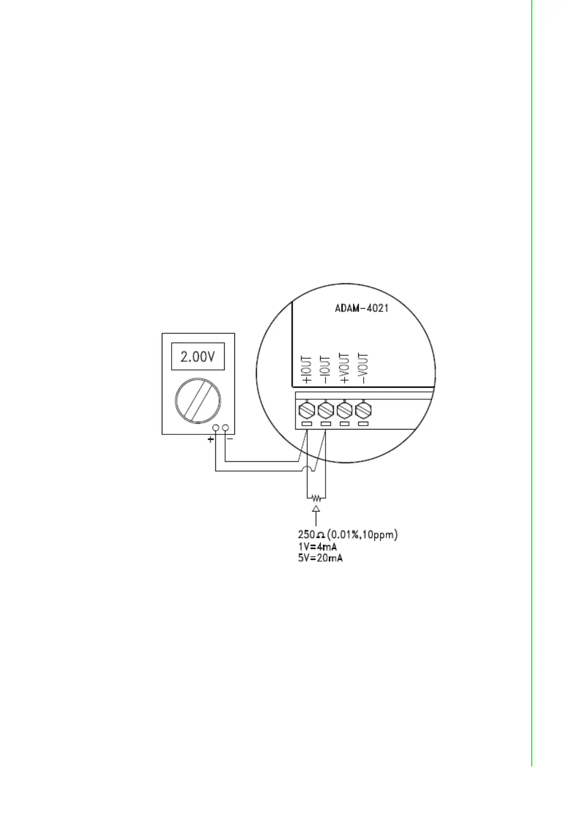
3. Connect either a 5-digit millimeter or voltmeter with a shunt resistor (250,
0.01% , and 10ppm) to the screw terminals of the module
Figure 8.6 Setup for Analog Output Calibration
4. Issue the Analog Data Out command to the module with an output value of 4
mA.
5. Check the actual output value at the terminals. If it does not equal to 4 mA, use
the “Trim” option in the “Calibrate” sub menu to change the actual output. Trim
the module until the millimeter indicates exactly 4 mA. In the case of using a
voltage meter with shunt resistor, the voltage meter should indicate exactly 1 V.
(When calibrating for 20 mA using voltage meter and shunt resistor, the correct
voltage would be 5 V.)
6. Issue the 4 mA Calibration command to indicate that the output is calibrated.
The calibrated parameters should be stored in the modules EEPROM.
7. Execute an Analog Data Out command with an output value of 20 mA, and the
output will approximately be 20 mA.
 Loading...