AIMB-584 User Manual 114
B.28 Alarm Board/CMM Power Connector (VOLT1)
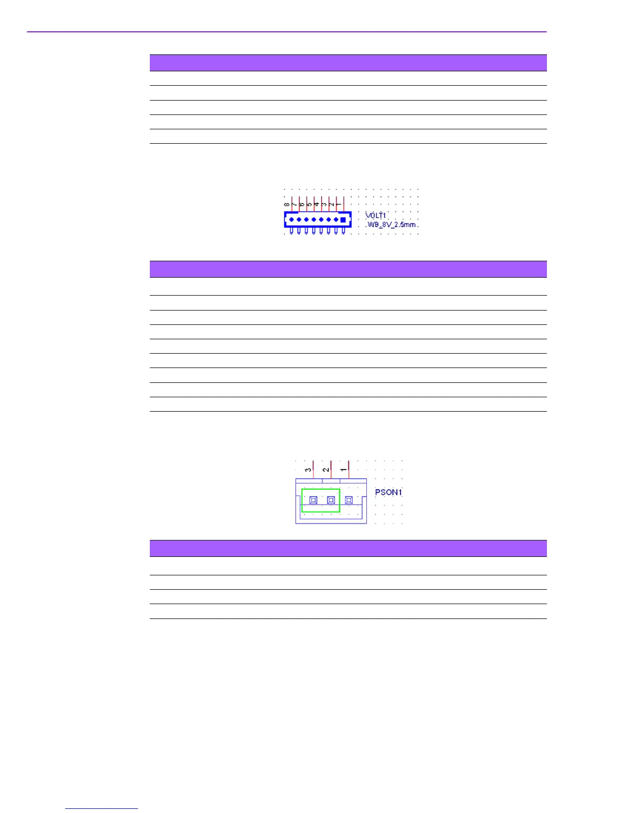
B.29 AT/ATX Mode Selection Connector (PSON1)
Note: ATX mode (2-3 short): System boots up by pressing power button.
AT mode (1-2 short): System boots up w/o pressing power button after turning on AC.
5 LAN1LED1 (LINK1000)
6 LAN2_LED2 (LINK1000)
7 LAN1_LED2 (LINK100)
8 LAN2_LED0 ((LINK100)
9 +V3.3_DUAL
Table B.27: LAN LED
Table B.28: Alarm Board/CMM Power Connector
Pin Pin Name
1 +5V Standby
2 GND
3GND
4 -5V
5+5V
6 +3.3V
7 -12V
8 +12V
Table B.29: AT/ATX Mode Selection Connector
Pin Pin Name
1AT
2 +3.3V
3ATX