115 AIMB-584 User Manual
Appendix B Pin Assignments
B.30 Front Panel (PWR LED&KB LOCK#) Pin Header
(JFP1)
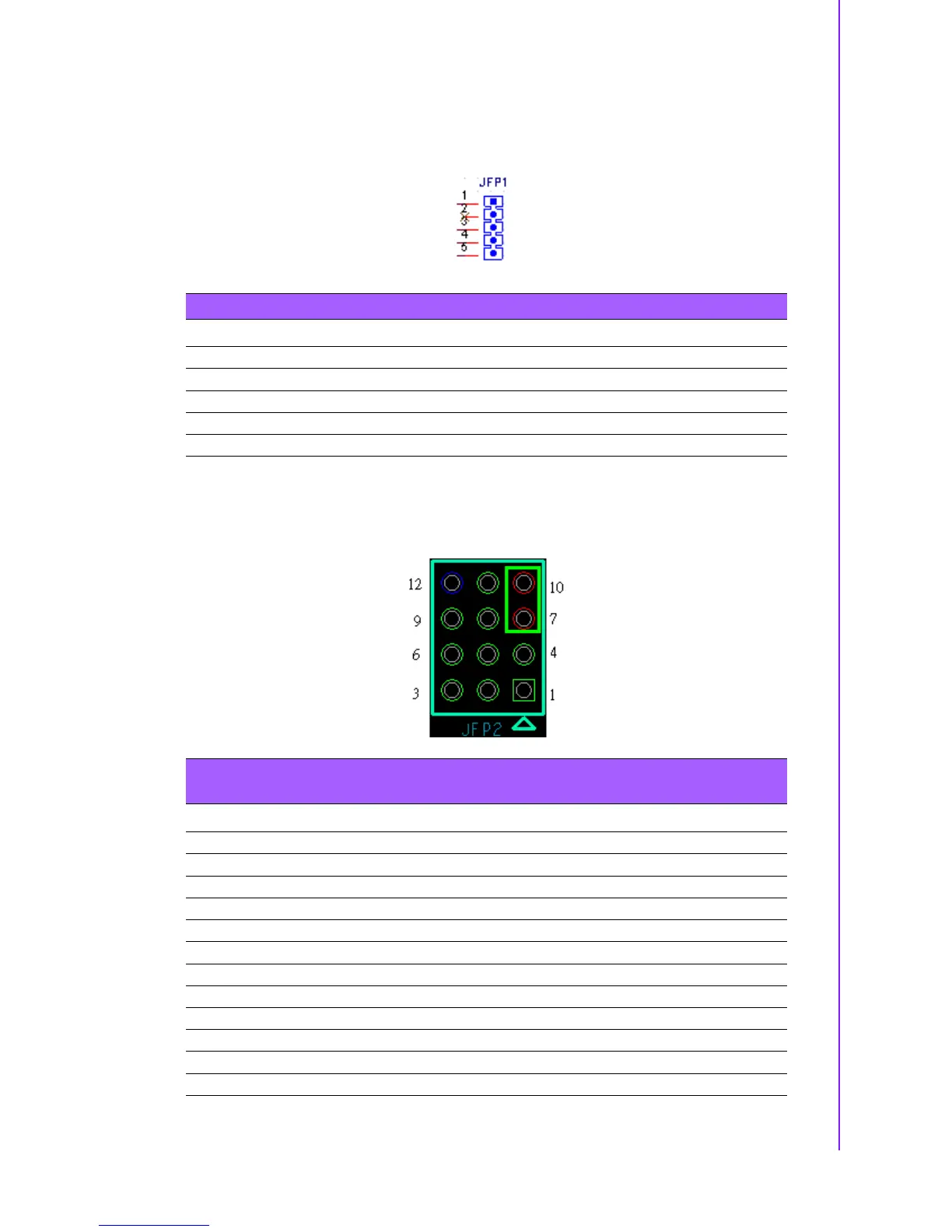
B.31 Power Switch/ Reset/ External Speaker/ SATA
HDD LED / SMBus Connector (JFP2)
Note: PWRBTN#(3-6) / RESET#(9-12) /HDD LED(2-5) / Serial bus from HW monitor IC(8-11)
/ Internal Buzzer(7-10 short) /External speaker(1-10 or 1-7).
Table B.30: Front Panel (PWR LED&KB LOCK#) Pin Header
Pin Pin Name
1 Power LED+ (+3.3V)
2NC
3 Power LED -
4 Keyboard Lock#
5 GND
Table B.31: Power Switch/ Reset/ External Speaker/ SATA HDD LED /
SMBus Connector
Pin Pin Name
1 Speaker +
2 HDD LED+
3 Power Button
4NC
5 HDD LED-
6 Power Button
7 Speaker -
8 H/W monitor IC_SDA
9 Reset Button
10 - Speaker
11 H/W monitor IC_SCL
12 Reset Button