AMT-70/AMT-73/AMT-75 Installation and Operation
Conversely, setting a maximum value of 255 ‘unmasks’ ALL bits in the Fault Mask Register and any bit
SET by the software becomes a fault condition.
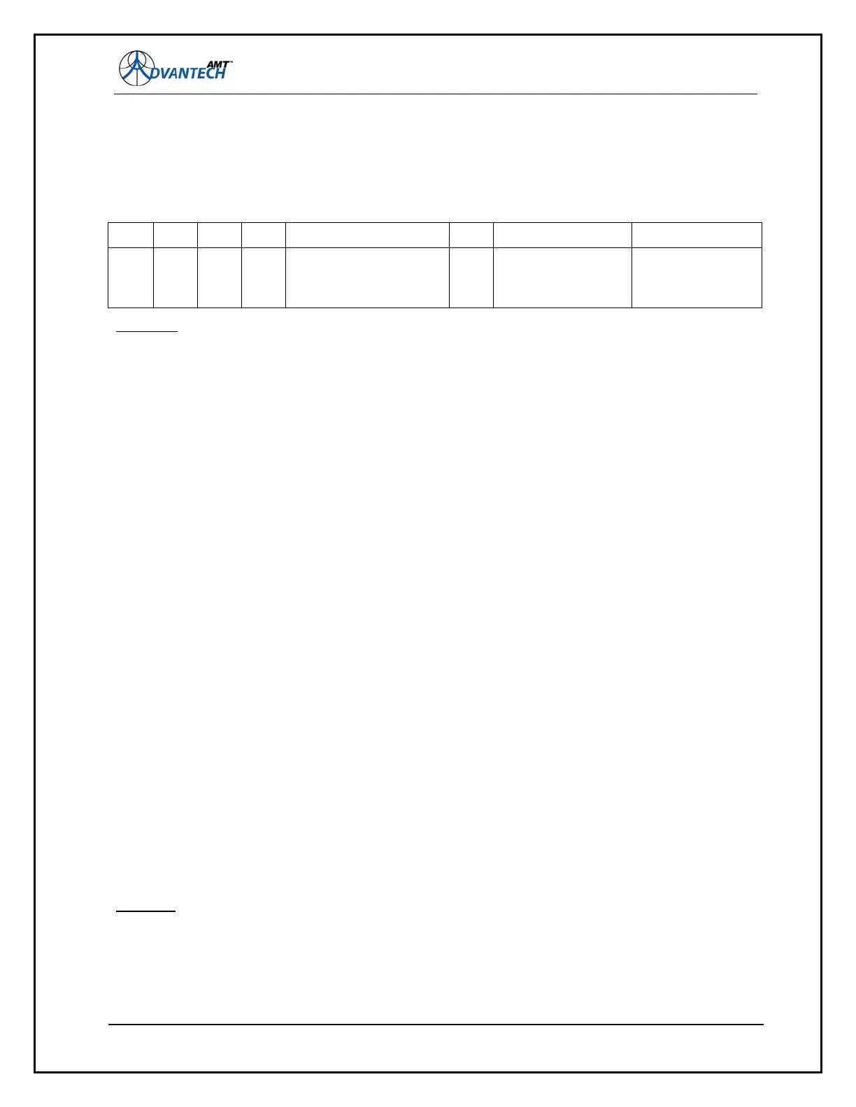
Figure 66: Redundancy Fault Mask Register
Examples:
# rdfltmask 1
Redundancy Fault Mask = 1
Setting the Fault Mask to 1 means when the Modulator output is disabled for some reason, a fault
condition will be generated on the redundancy output. If the other unit’s redundancy system is
enabled, reads good and the cables are connected, the other unit will actuate the switch upon reading
the fault condition.
# rdfltmask 8
Redundancy Fault Mask = 8
A fault status is generated for an internal Modulator failure, but NOT for a disabled output problem.
(Setting rdfltmask 9 will consider ALL conditions above for fault output).
NOTE: The modem MUST be rebooted for rdfltmask changes to take effect.
rdforce
Force the Redundancy switch to the ACTIVE (on-line) position for this unit. Note that this command
will work whether the Redundancy system is enabled or disabled.
A one-second drive pulse is fed to the RF switch. Also note that the drive is one-way, i.e. the unit can
only drive the RF switch to the ACTIVE state for itself.
The user must communicate with the other unit directly and use the same command to drive the RF
switch in the opposite direction.
Example
:
# rdforce
Switch is forced to ACTIVE for this unit
129
7 6 5 4 3 2 1
0
(LSB)
- - - -
MOD. NOT RUNNING/
UNLOCKED/ FPGA
FAILED
-
DEMOD COMMS
FAILED/
UNLOCKED
MOD. OUTPUT
ENABLED