Benchmark 1500 - 2000 Boilers
CHAPTER 3 – OPERATION
OMM-0097_0E AERCO International, Inc. • 100 Oritani Dr. • Blauvelt, NY 10913 Page 37 of 182
GF-142 Ph.: 800-526-0288 10/01/2015
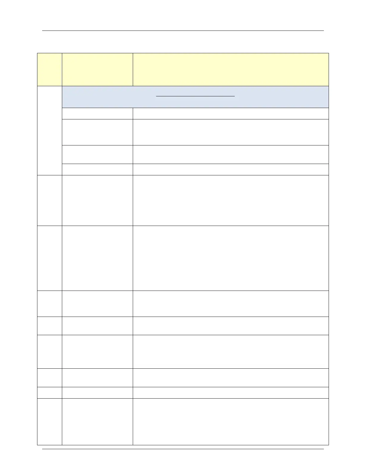
Table 3-1: Operating Controls, Indicators and Displays
ITEM
CONTROL,
INDICATOR OR
DISPLAY
FUNCTION
1
LED Status Indicators
Four Status LEDs indicate the current operating status as follows:
COMM
Lights when RS232 communication is occurring – see Item 4
MANUAL
Lights when the valve position (fire rate) is being controlled using
the front panel keypad. This mode of operation is for service
technician use only.
REMOTE
Lights
when the unit is being controlled by an external signal
from an Energy Management System
DEMAND
Lights when there is a demand for heat.
2
OUTLET
TEMPERATURE
Display
3–Digit, 7–Segment LED display continuously displays the outlet
water temperature. The °F or °C LED next to the display lights
to indicate whether the displayed temperature is in degrees
Fahrenheit or degrees Celsius. The °F or °C
operating in the DEADBAND mode.
On a BST Master, display flashes & shows header temperature.
3
VFD Display
Vacuum Fluorescent Display (VFD) consists of 2 lines each
capable of displaying up to 16 alphanumeric characters. The
information displayed includes:
• Startup Messages
• Fault Messages
• Operating Status Messages
• Menu Selection
4
RS232 Port
This port is used only by factory-
trained personnel to monitor
OnAER communications, in combination with the RS232 Adaptor
Cable (P/N
).
5
FAULT Indicator
Red FAULT LED indicator lights when a boiler alarm condition
occurs. An alarm message will appear in the VFD.
6
CLEAR Key
Turns off the FAULT indicator and clears the alarm message if
the alarm is no longer valid. Lockout type alarms will be latched
a
nd cannot be cleared by simply pressing this key.
Troubleshooting may be required to clear these types of alarms.
7
READY Indicator
Lights ON/OFF switch is set to ON and all Pre-Purge conditions
have been satisfied.
ON/OFF switch
Enables and disables boiler operation.
9
LOW WATER LEVEL
TEST/RESET
switches
Allows operator to test operation of the water level monitor.
Pressing TEST opens the water level probe circuit and simulates
a Low Water Level alarm.
Pressing RESET resets the water level monitor circuit.
Pressing the CLEAR key (item 6) resets the display.