AES 7707 RF Subscriber 15
Part No. 40-7707 Rev. 3a 10/23/2017
5. Wiring
5.1 Primary Power Wiring
Plug-In Transformer
Warning! Turn off or disconnect all power before attempting to connect the 7707 Subscriber. Do NOT apply
power until all accessories are properly connected.
For U.S. installations, use only one of the Class 2 Direct Plug-in Transformers listed below:
Important! All installations using plug-in transformers must use the AES Model 1640-ENCL Transformer
Enclosure for mechanical protection of the transformer. Wiring from the Transformer to the Subscriber must be
protected in conduit.
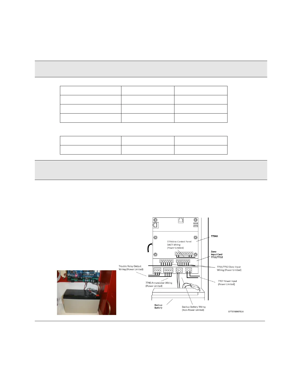
Refer to the wiring diagram for connection details, as well as for routing the battery, enclosure mounted antenna,
and the transceiver control cable. Leave a minimum of ¼ inch of spacing between non-power limited (battery
wiring) and power limited wiring as shown in the photo below and in the diagram below.
Figure 2. Wire Separation Non-Power Limited (left) Power Limited (right)
Earth Ground Connection
Earth ground and battery minus (-) are not separate connections in the 7707 Subscriber. Zone input terminals,
including the "G" terminals on zone input cards, are isolated from earth ground. Connect a suitable gauge wire as
specified in the applicable electrical code to the #8 ground stud as shown in the diagram below. Connect the wire to