AES 7707 RF Subscriber 32
Part No. 40-7707 Rev. 3a 10/23/2017
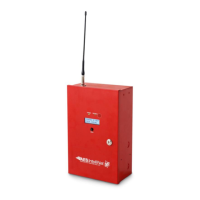
The IntelliPro panel will appear if a Model 7794A IntelliPro is installed in the Subscriber. The configuration menu
will appear as shown below:
Refer to the 7794A IntelliPro Fire Installation Manual (AES P/N 40-7794A) for instructions on configuring the
settings.
When done with changes, click the Save Changes button.
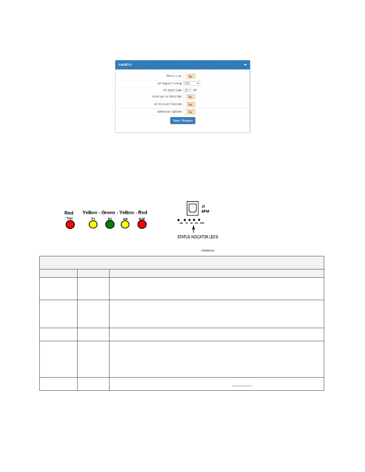
8.14 Status LED Indicators
The five LED indicators on the main circuit board of the Model 7707 show system status. The LEDs are located
near the top edge of circuit board below the J7/APM connector and near the RESET button as shown below:
Table 4. System Status LED Indicators
Status/troubleshooting indicator, “blink” (see ALM LED Blink Patterns table below)
Steady On = Waiting for acknowledgment of last transmission
Steady Blinking = Not on Network
Off = Normal
On = Radio transceiver receiving RF signal
NOTE: If RX is on steady for longer than 20 seconds, an interfering RF signal exists. Any RF
signals that are on the same frequency as the subscriber and which are strong enough to break
the squelch will also cause the RX light to remain on.
Blinking Continuously = Trouble Condition. Refer to Table 6 for trouble details.