AES 7707 RF Subscriber 45
Part No. 40-7707 Rev. 3a 10/23/2017
3. Connect conduit and/or pull wiring as required.
4. Remove the faceplate from the frame.
Note: Notice the routing of the Silence switch cable if applicable. In most cases, this cable need not be
disconnected. Use the slack cable to allow the faceplate to be moved out of the way.
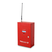
5. Terminate wires and connect the AES Model 7740 Local Annunciator, as shown in the following diagram.
The 7740 is powered and supervised by the AES Model 7707 Subscriber.
Figure 7. 7740 Wiring Diagram
6. Attach the frame to the box using frame screws.
7. Reinsert the faceplate into the frame.
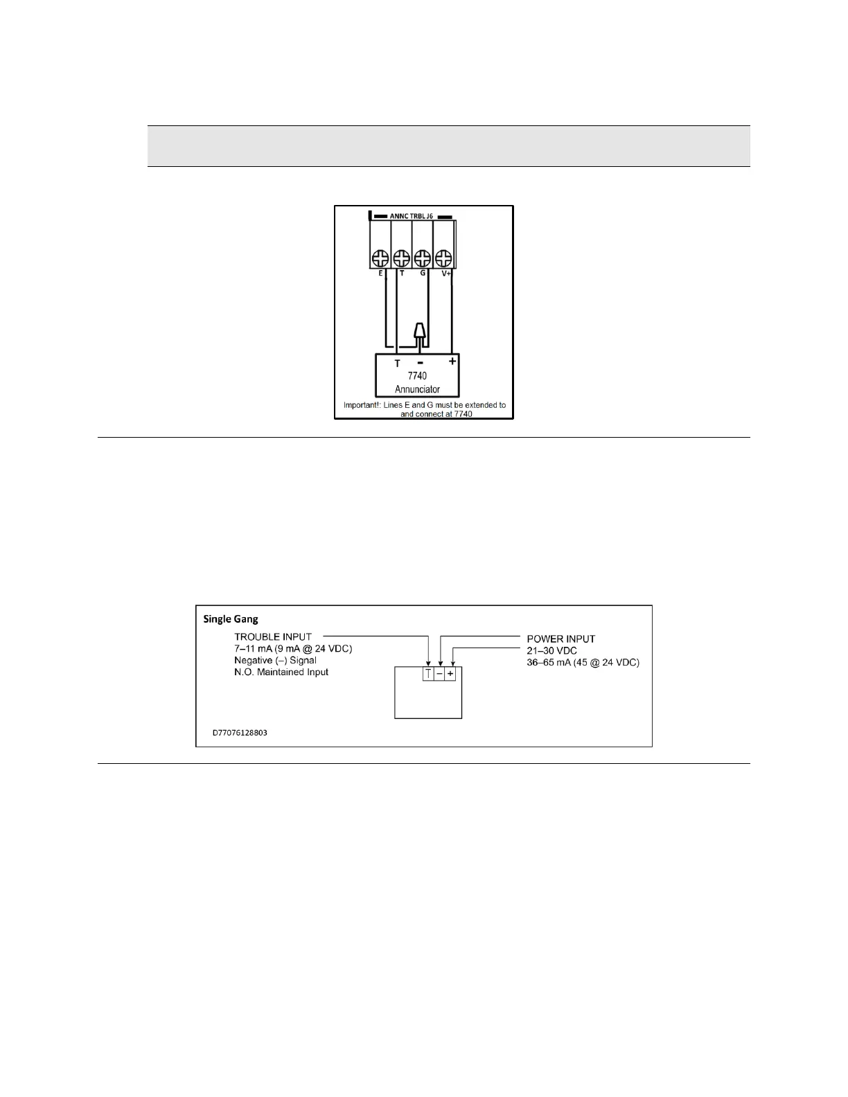
8. Single-gang installation only.
9. Review and confirm field wiring and setup.
10. Damage and/or malfunction can result from improper wiring and/or setup.
11. Place the cover over the faceplate and secure with cover screws.
12. Power up the system and test for proper operation of all zones and functions.
Figure 8. 7740 Wire Inputs
18. AES Corp. Contact Information
AES Corporation
285 Newbury Street
Peabody, Massachusetts 01960 USA
Website: http://www.aes-corp.com
AES corporate Phone: (800) 237-6387 (800) AES-NETS
USA (978) 535-7310
Fax: USA (978) 535-7313
Email: Check Website for latest email addresses