Theory of Operation 8
16900A, 16902A, and 16903A Service Guide 121
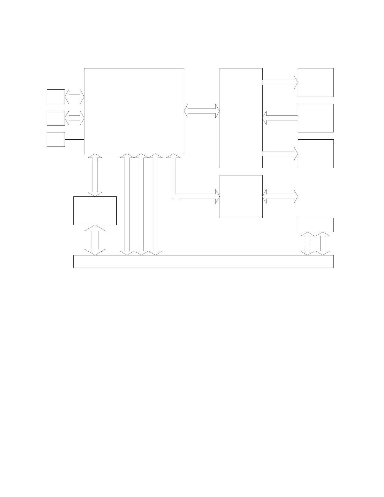
CPU subsystem
The CPU subsystem includes:
• CPU board (more on page 123)
• Disk drives (more on page 124)
• Power supply (more on page 124)
PCI board
For more information on the 16903A PCI board go to
page 124.
Module interface board (MIB)
The MIB subsystem block diagram shown here includes:
• Module bus FPGA (more on page 125)
• Video circuit (more on page 125)
• I/O FPGA (more on page 125)
• PLD (more on page 126)
CPU MOTHERBOARD
PCI Board
Module Interface Board
I/O Board
Front Panel
Interface Board
Keypad Board
12.1" Flat
Panel LCD
Display
12.1" Touch
Screen Grid
RS232
Grid Scan
Primary PCI Bus
DC FANS
CDROM IDE Bus
12V to 24V
IDE BUS- CDROM
Front
Panel
On/Off
Digital Video
RS232
+3.3V, +5V, +12V
Digital Video
CPU POWER CONNECTOR
CPU On/Off Reset
Hard Disk
Drive
P
O
W
E
R
Secondary PCI Bus
RS232
Bridge GPIO
+3.3V, +5V
Rear Panel Signals
IDE BUS
Trigger In
Trigger Out
Cal Out
Clock In
Target Control
 Loading...


