60 16900A, 16902A, and 16903A Service Guide
6 Replacing Assemblies
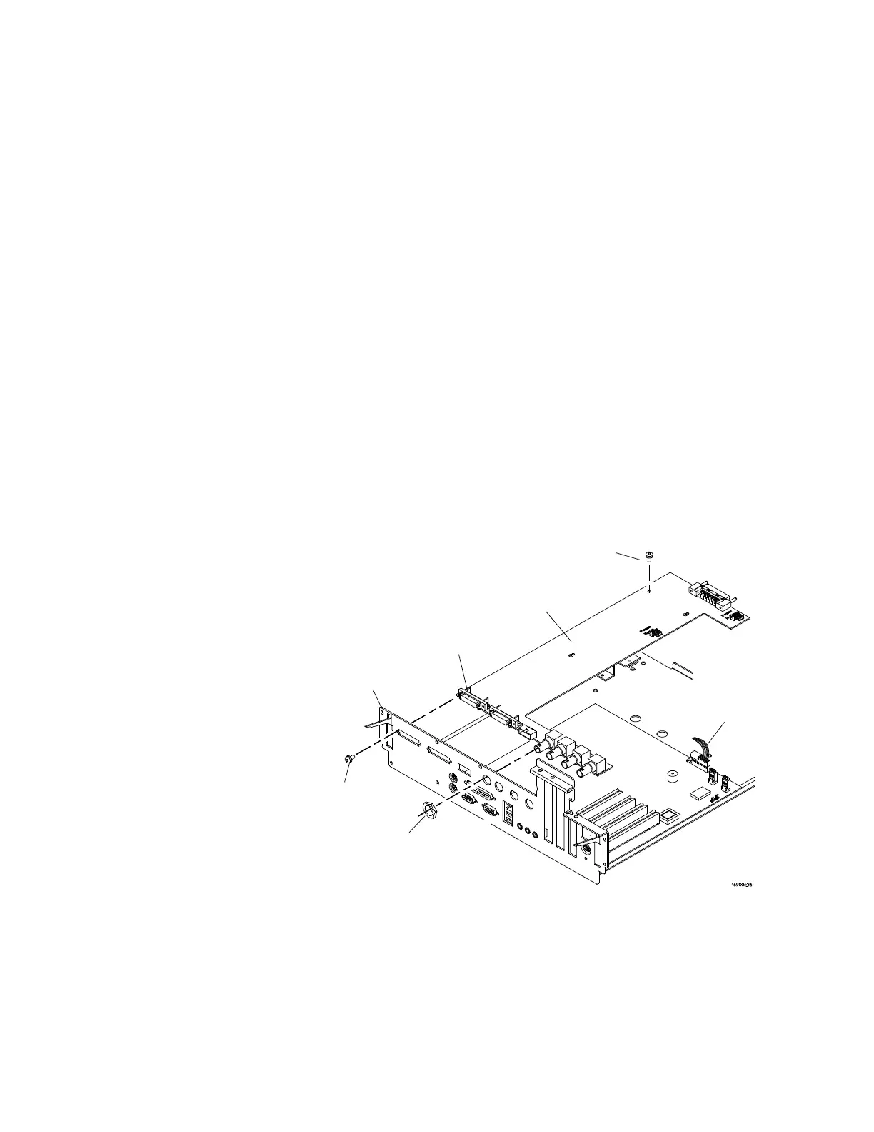
To remove and replace the I/O board
16900A and 16902A I/O board
1 Perform previous procedures:
• “To prepare the instrument for disassembly" on
page 48
• “To remove and replace the cover" on page 52
• “To remove and replace the CPU tray" on page 53
2 Disconnect the front panel reset cable.
3 Using a deep- well 13/16-inch nut driver, remove the hex
nuts that secure the BNC connectors to the rear panel.
4 Using a Pozidrive screwdriver, remove the 4 screws
securing the multiframe input/output connectors to the
rear panel.
5 Using a Torx T10 screwdriver, remove the screw securing
the I/O board to the CPU tray.
6 Reverse this procedure to install the I/O board.
T-10 Screw (1)
I/O Board
Multiframe
Connectors
16900/02A
Rear Panel
Pozidrive
Screws (4)
Hex Nuts (4)
Front Panel
Reset Cable