Replacing Assemblies 6
16900A, 16902A, and 16903A Service Guide 83
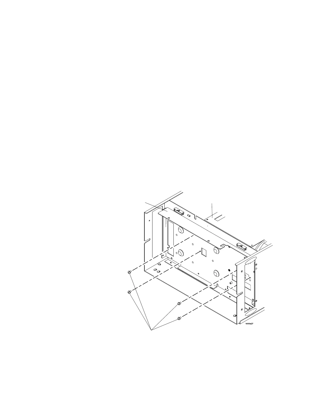
To remove and replace the module interface board
1 Perform previous procedures:
• “To prepare the instrument for disassembly" on
page 48
• “To remove and replace the cover" on page 52
• “To remove and replace the CPU tray" on page 53
• “To remove and replace the front panel assembly" on
page 64
• “To remove and replace the power supplies" on page 77
• “To remove and replace the card cage and fans" on
page 80
2 Ensure that all cables are disconnected from the module
interface board.
3 Using a Torx T10 screwdriver, remove the 4 screws
securing the card cage to the front strut.
Front
Strut
Card
Cage
T10 Screws (4)