64 16900A, 16902A, and 16903A Service Guide
6 Replacing Assemblies
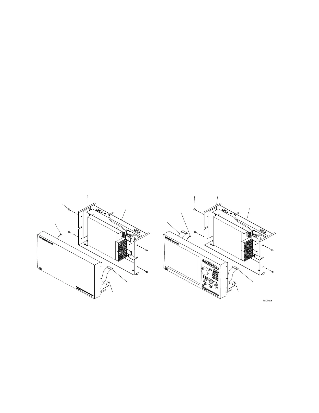
To remove and replace the front panel assembly
1 Perform previous procedures:
• “To prepare the instrument for disassembly" on
page 48
• “To remove and replace the cover" on page 52
2 Disconnect the following cables from the module interface
board:
• Front panel cable (16902/03A only)
• Power On|Off cable
• CD- ROM cable
3 Using a Torx T10 screwdriver, remove 4 screws that
secure the front panel to the chassis.
4 Remove/replace the front panel assembly.
5 Reverse this procedure to install the front panel assembly.
T10
Screws (4)
T10
Screws (4)
16902/03A
Chassis
16900
Chassis
Alignment
Pin
CD-ROM
Cable
Module
Interface
Board
Power
On|Off
Cable
Alignment
Pin
CD-ROM
Cable
Power
On|Off
Cable
Front
Panel
Cable
Module
Interface
Board

 Loading...


