Troubleshooting 5
16900A, 16902A, and 16903A Service Guide 27
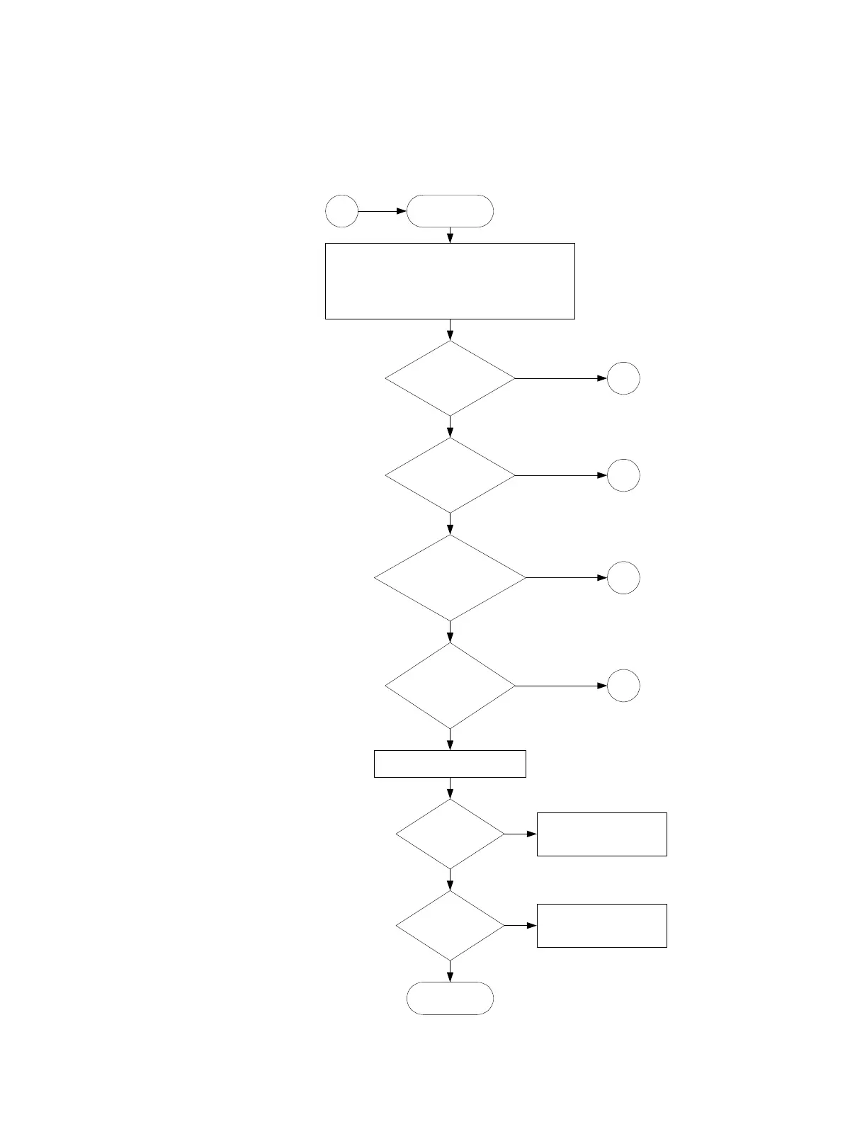
Figure 1 16900A and 16902A Troubleshooting Flowchart
Are the
fans turning &
power on?
Is the
display screen
readable?
Does
the instrument finish
booting to windows
login?
Start
Attach keyboard, mouse and power cord.
Attach the external display for 16900A.
Remove all user-installed PCI cards (see'To
remove & replace optional interface cards' in
chapter 7). Apply power.
Does
the logic analyzer
application
start?
Run the module self tests.
Do
the self tests
pass?
1
2
3
No
No
Is the
problem still
present?
Done.
4
No
5
No
No
Yes
Go to module
troubleshooting.
Call Agilent support.
Yes
Yes
Yes
Yes
Yes
No